Compression connector with integral coupler
- Summary
- Abstract
- Description
- Claims
- Application Information
AI Technical Summary
Benefits of technology
Problems solved by technology
Method used
Image

Examples
Embodiment Construction
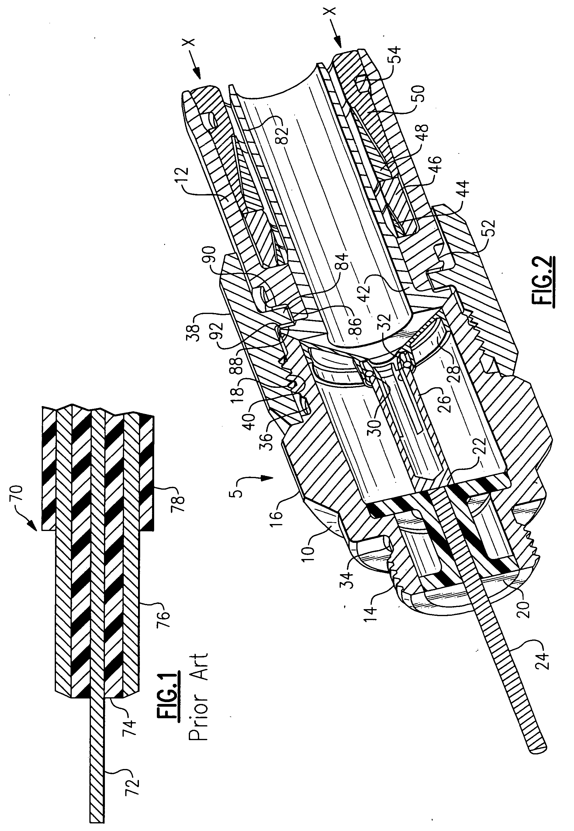
[0015] Referring to FIG. 1, a cross-section of a coaxial cable 70 is shown. A center conductor 72 is surrounded by a dielectric 74 which in turn is surrounded by a ground sheath 76. These layers are then surrounded by an outer coating 78. Center conductor 72 and ground sheath 76 must be electrically conductive, while dielectric 74 must be an electrical insulator. Cable 70 is shown in a “prepared” configuration, with center conductor 72 extending from dielectric 74 and ground sheath 76, and outer coating 78 pulled back from the other layers.
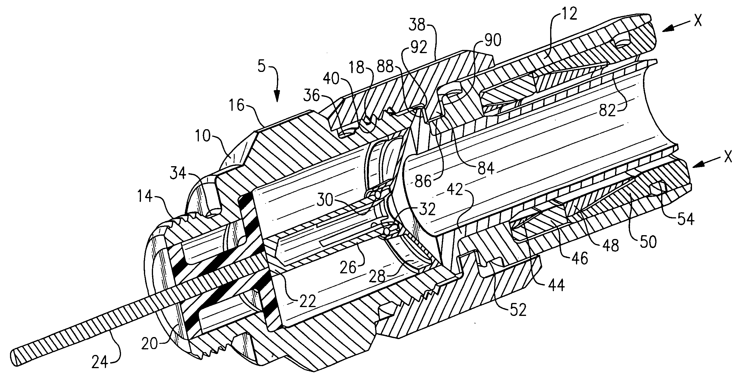
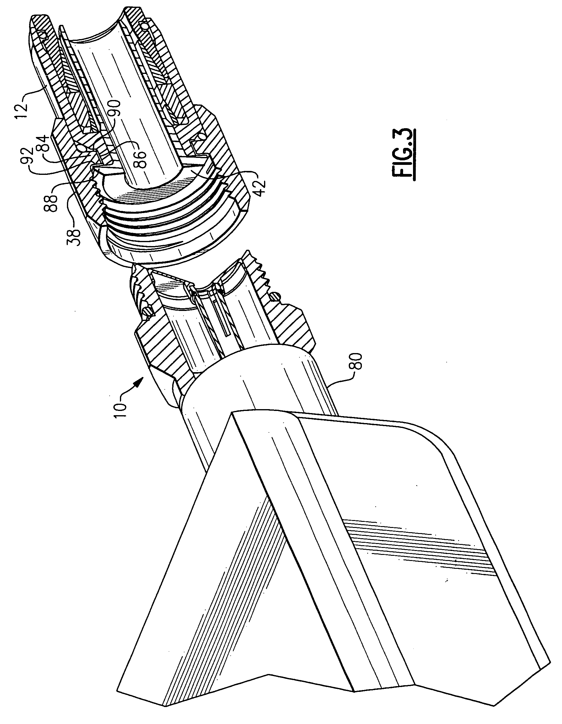
[0016] Referring to FIG. 2, an embodiment of a coaxial cable connector 5 is shown. A front body 10 interconnects with a back body 12 via a coupler nut 38. Front body 10 includes a plurality of threads 14 which screw connector 5 to an equipment port 80 (FIG. 3). Front body 10 further includes an annular groove 34 which holds an O-ring (not shown) which seals front body 10 to equipment port 80 when connector 5 is installed, in addition to an annula...
PUM
 Abstract
Description
Claims
Application Information