
Device for use in intraluminal grafting

Inactive Publication Date: 2005-08-04
GORE ENTERPRISE HLDG INC
View PDF6 Cites 56 Cited by
  • Summary
  • Abstract
  • Description
  • Claims
  • Application Information

AI Technical Summary

Benefits of technology

[0016] The main body of the device may be substantially cylindrical wherein the entire outer wall of the cylindrical main body engages the wall of a vessel to effectively seal the device of the present invention in said vessel. In this manner, the flow of blood in a diseased vessel is channeled through the intraluminal graft or stent thereby preventing leakage of blood into the damaged part of the vessel. The device essentially forms a collar or ring around one or both ends of the intraluminal graft or stent. Alternatively, the device may form a collar or ring around a portion of the length of said intraluminal graft or stent, between said ends.
[0058] The radial expansion of the intraluminal graft or stent may further secure the outer wall of the main body of the device to a wall of the vessel, that is, an added force is applied to secure the device within the vessel.

Problems solved by technology

Difficulties often arise in the placement and sealing of such grafts and, further, in maintaining the graft within a vessel of a patient.
Conventional intraluminal grafts often do not align or seal well with such a diseased or anatomically unique vessel structure.
Accordingly, such ill-fitting grafts have a tendency to slip within the vessel, reducing the effectiveness of the graft and in some cases causing the graft to occlude an opening of a pre-or post-branching vessel.
Such a drawback may stem from the fact that most conventional intraluminal grafts are made from material having properties to optimise blood flow through the graft.
These materials, however, may not be particularly suitable for securing and sealing the graft within a vessel.
However, such a coating on the outside of an intraluminal graft greatly increases the diameter of the compressed graft.
In turn, the graft does not fit within an introducer catheter and is too bulky to be introduced into a vessel of a patient using minimally invasive techniques.

Method used


Image

  • Device for use in intraluminal grafting
  • Device for use in intraluminal grafting
  • Device for use in intraluminal grafting

Examples


Embodiment Construction

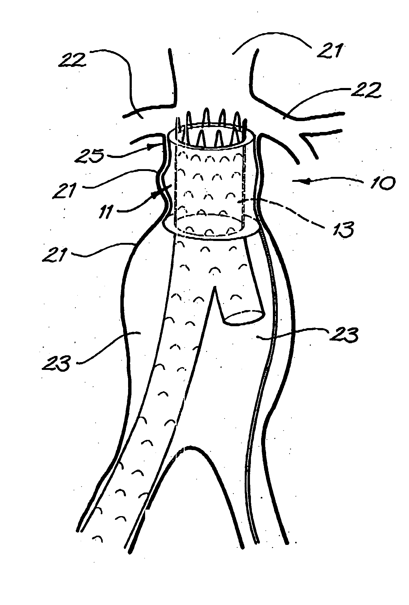
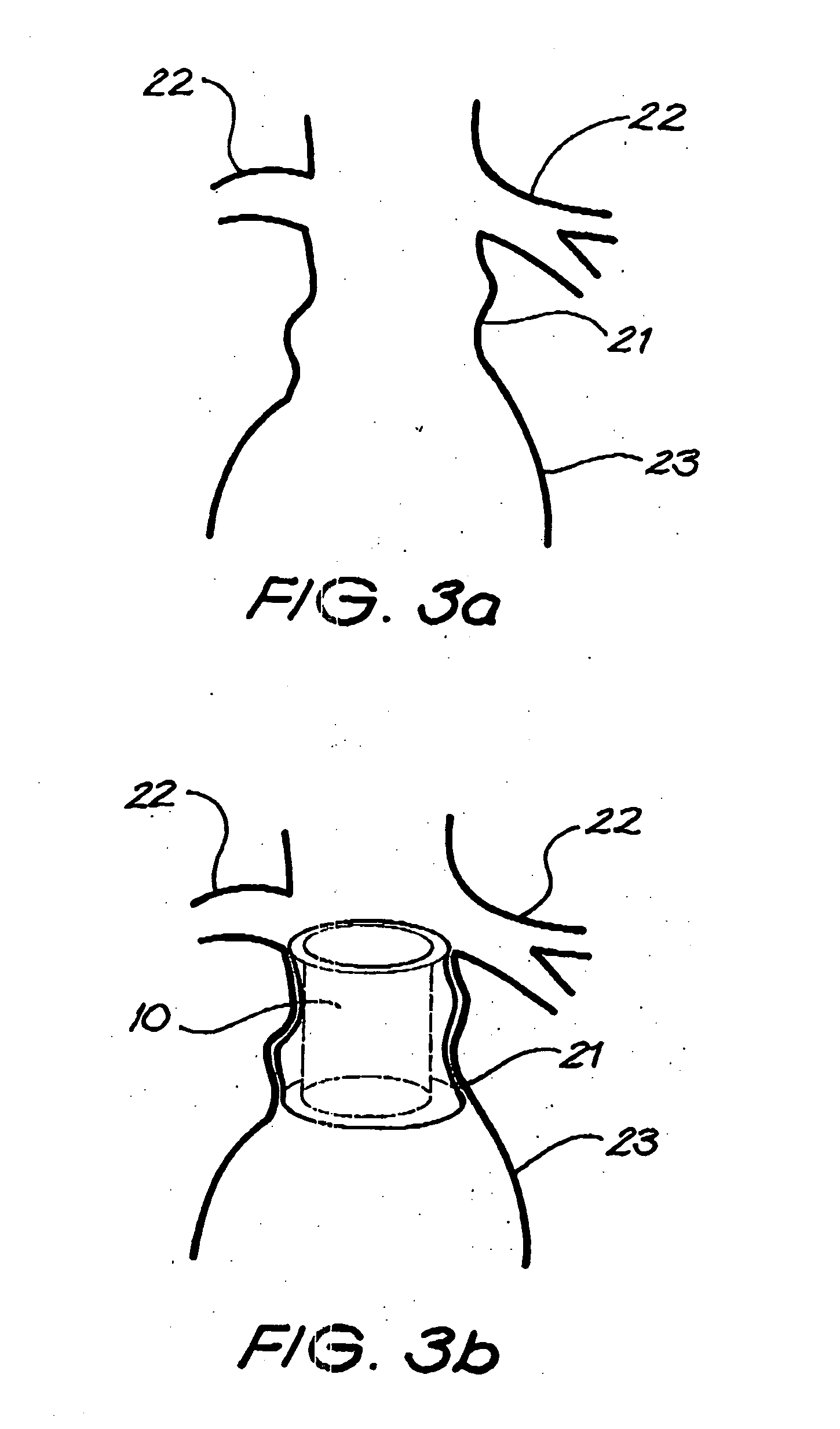
[0075] The intraluminal device of the present invention is generally depicted as in the accompanying drawings. The device 10 has a main body 11 with a receiving region 12 adapted to receive part of an intraluminal graft 13 therein.

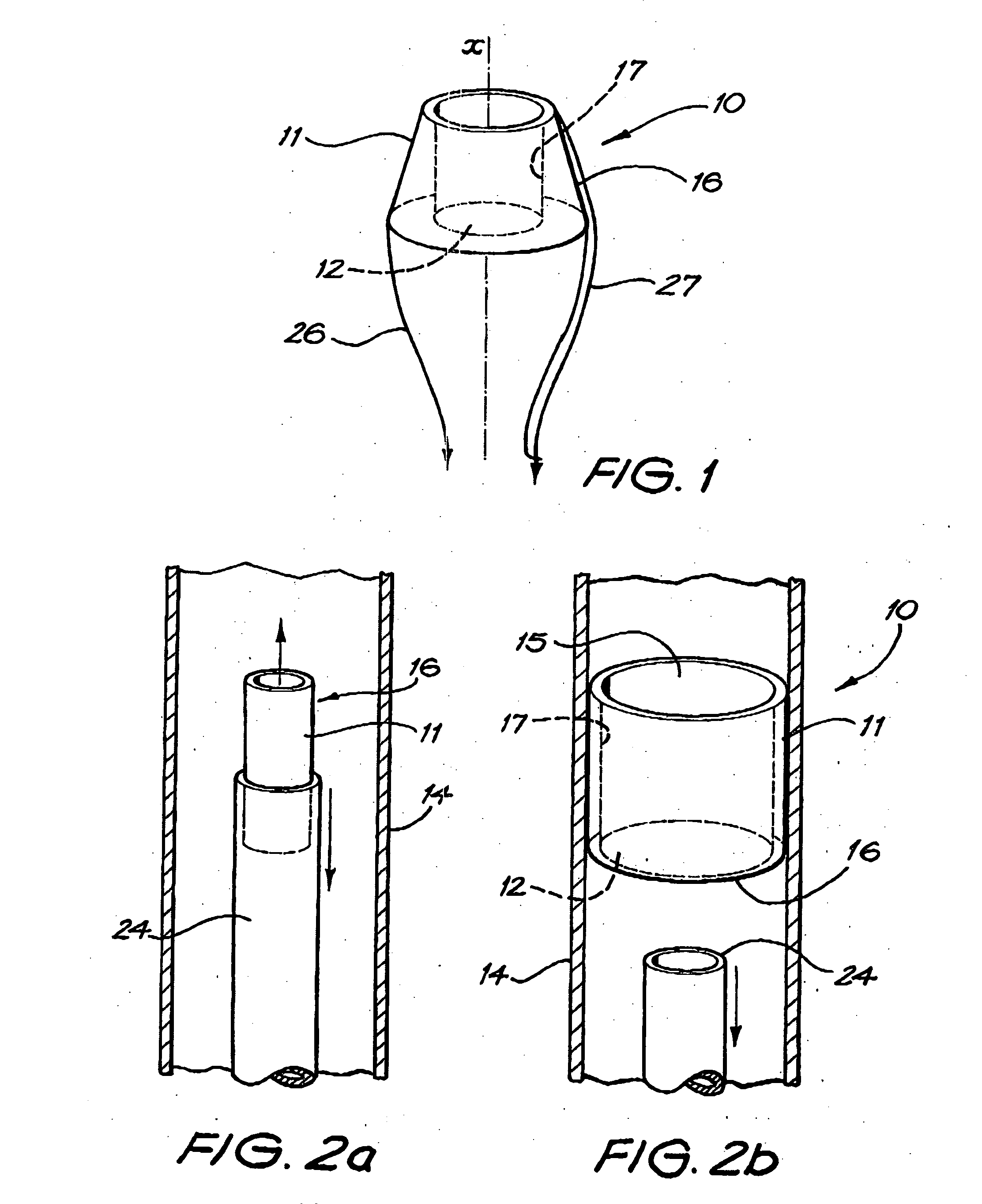
[0076] As shown, the main body 11 capable of expanding or being expanded from a first radially compressed state (shown in FIG. 2a) to a second radially expanded state (shown in FIG. 2b) such that when in the second radially expanded state, the main body 11 engages a wall of a vessel 14 in which it is positioned.

[0077] In each depiction, the main body 11 has an internal lumen 15 extending therethrough. The internal lumen 15 receives the intraluminal graft 13.

[0078] In FIGS. 2a and b, the main body 11 of the device 10 can be seen to be substantially cylindrical, As shown in FIG. 1, the main body 11 of the device 10 may be of a generally frusto-conical configuration. In this embodiment, it can be seen that the main body 11 has an outer wall 16 for engaging...


PUM


Abstract

An engagement device for an intraluminal graft or stent which aids in securing and sealing the graft or stent in place within a vessel of a patient. The device comprises a main body which is radially expandable within the vessel wherein the main body also includes a receiving region to receive and engage the intraluminal graft or stent.

Description

FIELD OF THE INVENTION [0001] The present invention relates to a device for use in intraluminal grafting and particularly to a device which secures an intraluminal graft or stent within a vessel of a patient. BACKGROUND ART [0002] Intraluminal grafts are used in the treatment of several diseases including aneurysmal disease and stenotic disease. The graft is typically used to by-pass a diseased area of a vessel thereby enabling the flow of blood therethrough. [0003] Difficulties often arise in the placement and sealing of such grafts and, further, in maintaining the graft within a vessel of a patient. This may be the case either because the diseased vessel has an atypical configuration or simply because a particular individual has a unique anatomy. For example, the vessel may bulge, form a cone shape or may branch from a first vessel at more of an angle than would be expected. [0004] Conventional intraluminal grafts often do not align or seal well with such a diseased or anatomicall...

Claims


Application Information

Patent Timeline
IPC IPC(8): A61F2/06A61F2/07A61F2/848A61F2/89
CPCA61F2/064A61F2/07A61F2230/0054A61F2002/8486A61F2/89A61F2002/065A61F2/95
Inventor WHITE, GEOFFREY H.
Owner GORE ENTERPRISE HLDG INC
Learn More