Ball and seat valve assembly and downhole pump utilizing the valve assembly

Active Publication Date: 2022-02-10
NELSON II JOE A
View PDF0 Cites 0 Cited by
  • Summary
  • Abstract
  • Description
  • Claims
  • Application Information

AI Technical Summary

Benefits of technology

The present invention is about improving a downhole pump by reducing wear and tear caused by sand and debris. The invention achieves this by using a special ball and seat valve assembly and a piston with an actuator that engages the ball and prevents it from wearing the valve components. The valve is designed to have a greater sealing area and can be struck asymmetrically with respect to the vertical axis through the center line of the ball. The piston includes an actuator with umbrella-shaped discs to prevent ball from plugging in the valve cage. The invention also includes a hollow tubular member with an interior wall and a sealing member that seals the entire internal cross-sectional area of the tubular member.

Problems solved by technology

Unfortunately, sometimes formation pressure may be initially too low to produce the formation, or may decline to that point as hydrocarbons are produced from a formation.
One problem encountered by sucker rod pumps is caused by the wear of the ball and seat valves.
The fluid produced from many geological formations contains minute, abrasive particles, such as sand, which lodge between the ball and seat and wear away the valve components.
In some wells, where the production fluid is particularly sandy or corrosive, these pumps must be replaced at frequent intervals.
It is, of course, evident that removing and repairing or replacing a pump, and the associated losses of lost production time during the repair or replacement process, can be significant expense factors.
Another problem associated with such conventional ball and valve sub-surface oilfield pumps is generally known as “gas locking”.
However, in a well producing both oil and gas, the chamber between the traveling valve and the standing valve, frequently fills with gas, and due to the compressibility of gas, the downstroke of the traveling valve may not build up sufficient pressure in the chamber below the traveling valve to act upwardly on the ball of the traveling valve to overcome the immense pressure of the fluid column above the traveling valve which acts downwardly on the ball of the traveling valve, resulting in the ball of the traveling valve remaining in the closed seated position during the downstroke.
Thus, the gas between the standing valve and the traveling valve merely compresses and expands with each stroke of the pump, producing the operational failure of the pump known as “gas locking”.
The additional problem is the adhesion of the ball to the seat by surface tension created by the oil under great pressure.
Another problem is holes in casing that require a packer to isolate leak where all fluid must go through pump including large volume of gas.
Even another problem associated with such conventional ball and valve sub-surface oilfield pumps is generally known as “fluid pounding.” This fluid pounding occurs when the pump does not fill completely with liquid during the upstroke, resulting in the formation of a low pressure gas cap in the top of the pump chamber between the traveling valve and the standing valve.
However, given the expansion and contraction of the sucker rods, the traveling valve may not reach the rod, or may extend past the rod, damaging the valve.
However, since the piston cross-sectional area affected by the pressure between the standing valve and the piston is equal to the cross-sectional area of the traveling valve seat, no mechanical advantage is provided by the arrangement of Horton.
Thus, Horton suffers from “gas locking” to the same extent as conventional traveling valves.
Additionally, the Horton traveling valve and the rod assembly are not mounted below the bottom of the plunger, and thus must be made of materials strong enough to withstand the rigors of operation of the pump.
Currently there are issues for pumping under a packer that forces all fluid to go through the pump.
Increased force is required to hold the valve open due to large amount of gas being pumped.

Method used


Image

  • Ball and seat valve assembly and downhole pump utilizing the valve assembly
  • Ball and seat valve assembly and downhole pump utilizing the valve assembly
  • Ball and seat valve assembly and downhole pump utilizing the valve assembly

Examples


Embodiment Construction

[0041]Referring now to the figures the present invention will be shown and described in detail. Fluid is defined as gas, water, oil or mixture thereof.

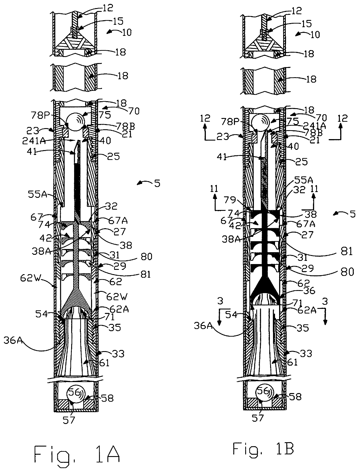
[0042]FIGS. 1A and 1B are cross-sectional views of reciprocating fluid pump 10 of the present invention showing piston 40 in a lower and in an upper position, respectively.

[0043]In general, sucker rod 322 connects to and actuates pump pull rod 12. Sucker rod 322 is actuated from the surface by any of the well known means, usually a “rocking horse” type pump jack unit . . . .

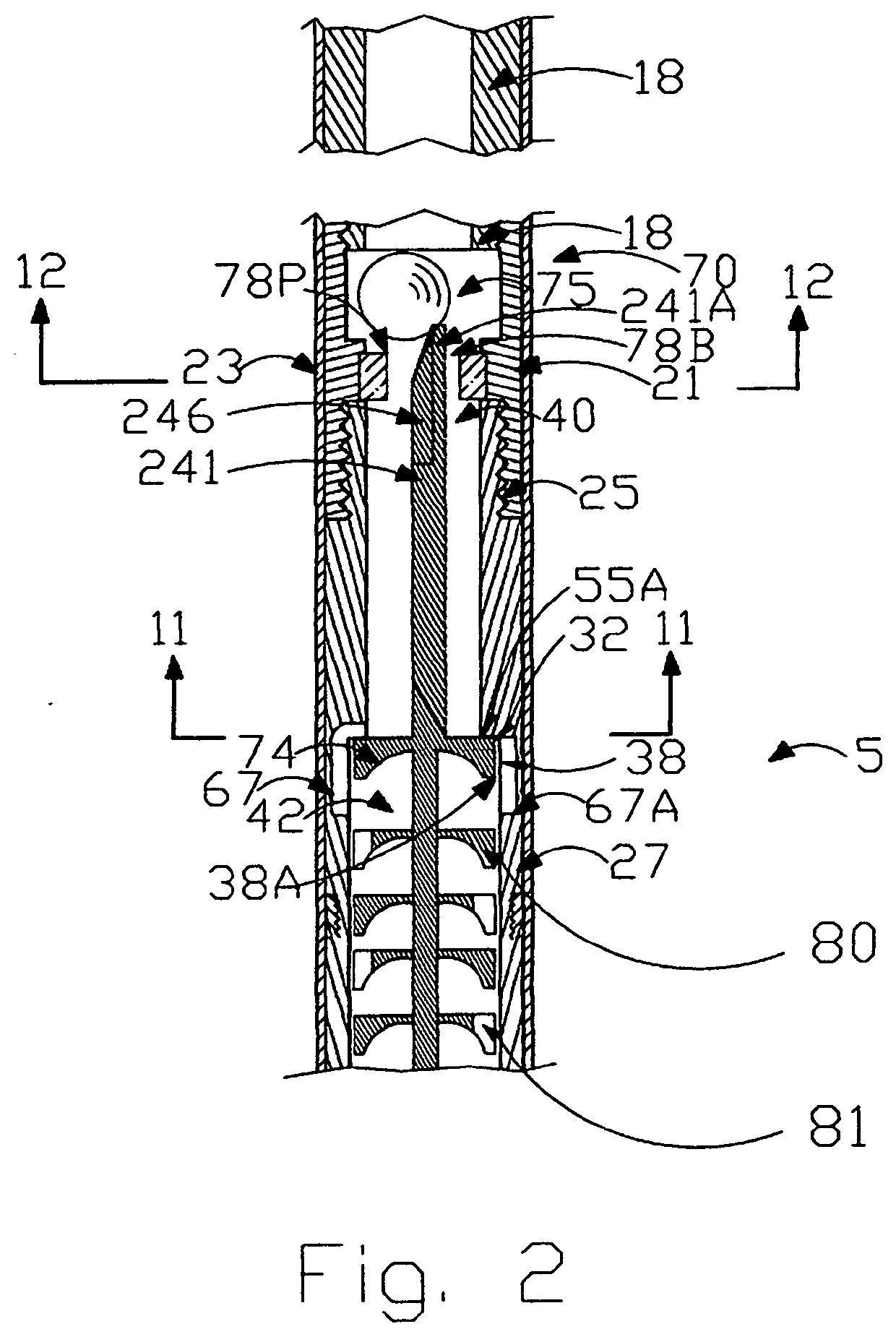
[0044]Threaded connection 25 joins traveling valve cage 21 with tubular housing 27, which extends downwardly to lower housing 29 by threaded connector 31. Housing 29 in turn extends downwardly and connects to housing 33 through threaded connector 35. It is to be understood that housings 27, 29 and 33 form hollow tubular housing assembly 5 which is adapted for attachment to the traveling valve 70.

[0045]At the bottom of barrel 23 is positioned conventional standing v...


PUM


Abstract

Disclosed is a work for oilwell plunger pumping under a packer system used to increase the wear life of API ball and seat valves and of ball and seat valves seat utilizing a piston actuator mechanism to unseat the ball from the seat, which during operation, create turbulent flow within the housing to increase force to move piston actuator like rifle bullet or weighted blow dart in dynamic high velocity high impact in stages to overcome hydraulic head and surface tension between ball and seat. Also disclosed umbrella shaped disks on the piston actuator for increased force to be used in both insert and tubing type down hole plunger oil well pumps. The labyrinth of fluid passages that are rectangular channels not holes help keep ball off its seat for complete down stroke and keep solids in suspension to prevent plugging of API ball in API valve cage. Part of the art is based on “Hydraulic Jump” theory by Leonardo Di Vinci in 1500's where thin film at the surface, greatly increases force due to physical changes to fluid at high speeds hitting objects.

Description

BACKGROUND OF THE INVENTION1. Field of the Invention[0001]The present invention relates to valves and pumps. In another aspect, the present invention relates to ball and seat valves, and to pumps utilizing said valves. In even another aspect, the present invention relates to ball and seat valves utilizing a piston mechanism to unseat the ball from the seat, and to down hole pumps utilizing said valves. In still another aspect, the present invention relates to ball and seat valves including components to increase their wear life. In yet another aspect, the present invention relates to ball and seat valves including components to create turbulent flow for movement of actuator piston. Also present invention breaks the surface tension between traveling valve ball and seat while overcoming the hydrostatic forces in the tubing above the down hole oil well pump. Fluid flow is through rectangular channels not round holes to reduce flashing.2. Description of the Related Art[0002]In the produ...

Claims


Application Information

Patent Timeline
IPC IPC(8): E21B34/08E21B43/12
CPCE21B34/08E21B2200/04E21B43/126E21B34/14
Inventor NELSON, II, JOE A.
Owner NELSON II JOE A
Why Eureka
Try Eureka