
Information processing apparatus operable to switch operating systems

Inactive Publication Date: 2005-08-04
PANASONIC INTELLECTUAL PROPERTY CORP OF AMERICA
View PDF4 Cites 40 Cited by
  • Summary
  • Abstract
  • Description
  • Claims
  • Application Information

AI Technical Summary

Benefits of technology

[0016] In view of the problem stated above, an object of the present invention is to provide an information processing apparatus that has a plurality of operating systems and switches between operating systems while processing is performed, wherein it is possible to protect information owned by each operating system from other operating systems.

Problems solved by technology

According to the technique disclosed in Patent Document 1, however, the information owned by each operating system is not necessarily protected from other operating systems.
There is possibility that operation of an operating system may impede operation of another operating system or may destruct information owned by another operating system.

Method used


Image

  • Information processing apparatus operable to switch operating systems
  • Information processing apparatus operable to switch operating systems
  • Information processing apparatus operable to switch operating systems

Examples


first embodiment

[0088] The following describes the information processing apparatus 100 as the first embodiment of the present invention, with reference to the drawings. In this description of the invention and the drawings, an “operating system” is sometimes simply referred to as an “OS”.

Configuration

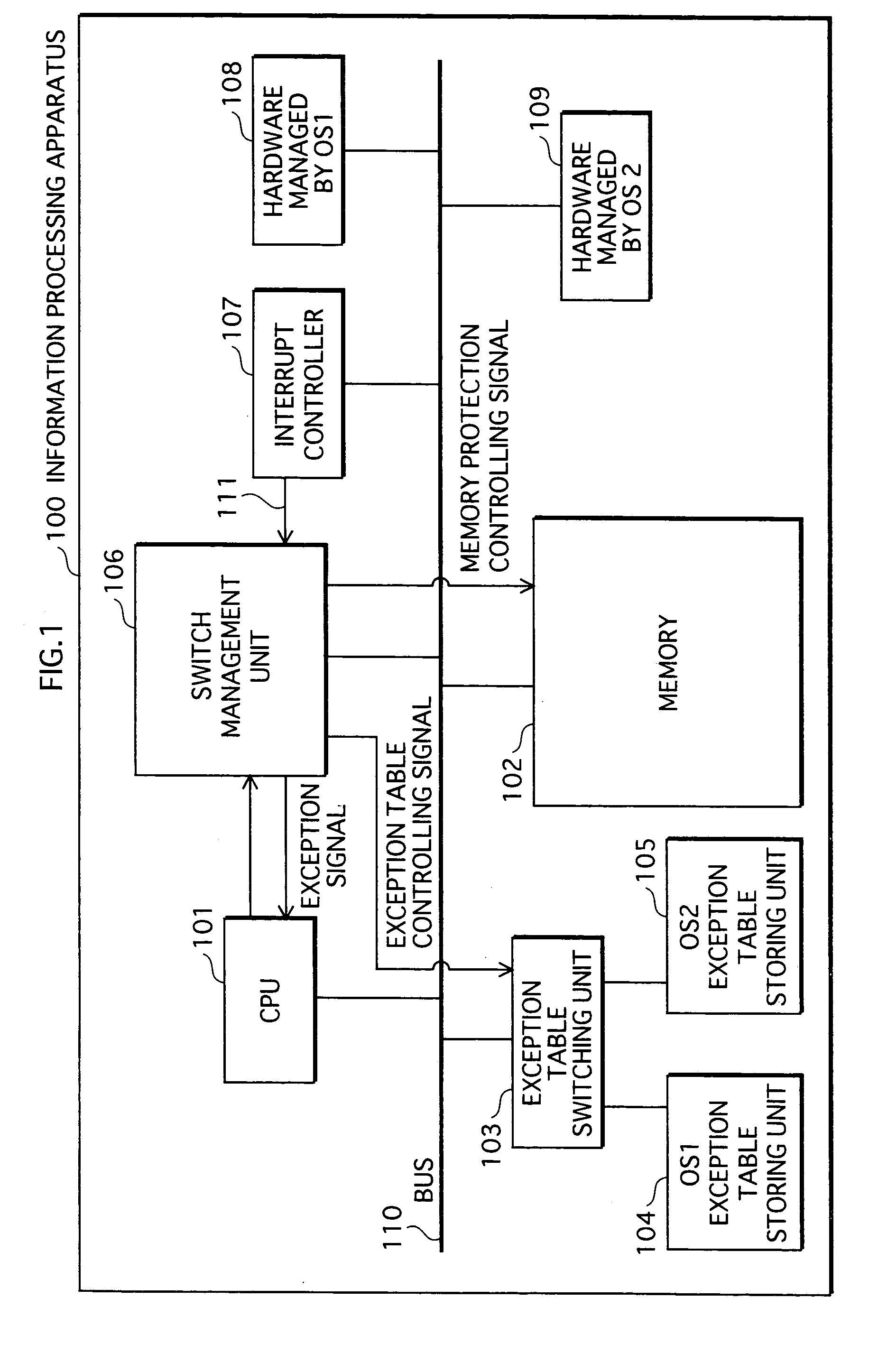
[0089]FIG. 1 is a functional block diagram that shows the configuration of the information processing apparatus 100 in terms of its functions.

[0090] As shown in the drawing, the information processing apparatus 100 comprises: a CPU (Central Processing Unit) 101; a memory 102; an exception table switching unit 103, an OS 1 exception table storing unit 104; an OS 2 exception table storing unit 105; a switch management unit 106, an interrupt controller 107, hardware managed by the OS 1108, hardware managed by the OS 2109, and a bus 110.

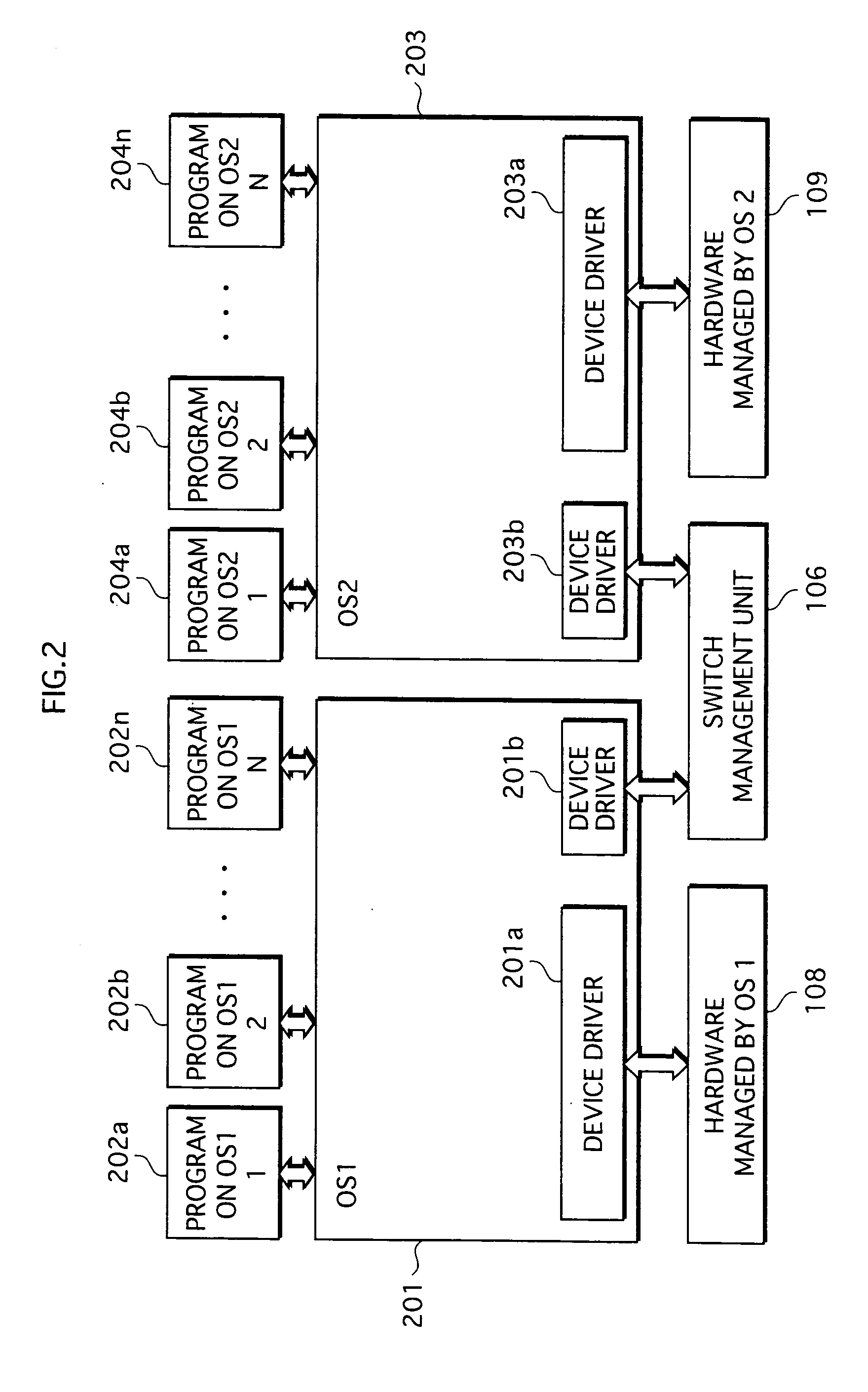
[0091]FIG. 2 shows the software configuration of the information processing apparatus 100.

[0092] As shown in the drawing, the software in the information processing ...

second embodiment

[0178] The following describes the information processing apparatus 100a as the second embodiment of the present invention, with reference to the drawings.

Configuration

[0179]FIG. 16 is a functional block diagram that shows the configuration of the information processing apparatus 100a in terms of its functions.

[0180] As shown in the drawing, the information processing apparatus 100a comprises: a CPU 101a; a memory 102a; an exception table switching unit 103a, an OS 1 exception table storing unit 104a; an OS 2 exception table storing unit 105a; a switch management unit 106a, an interrupt controller 107a, hardware managed by the OS 1108a, hardware managed by the OS 2109a, a bus 110a, a debugger invalidation circuit 112a, and a debugger interface 113a.

[0181] The difference from the configuration of the information processing apparatus 100 is that the information processing apparatus 100a comprises the debugger invalidation circuit 112a and the debugger interface 113a.

[0182] Expla...

modification example 1

[0253] The information processing apparatus 100a of the second embodiment has an arrangement wherein the software inquires of the interrupt controller 107a about the cause of the interrupt; however, it is acceptable to have an arrangement wherein hardware checks for the cause of an interrupt. The following describes information processing apparatus 100b as a modification example of the information processing apparatus 100a.

[0254]FIG. 25 is a functional block diagram that shows the configuration of the information processing apparatus 100b in terms of its functions.

[0255] As shown in the drawing, the information processing apparatus 100b comprises: the CPU 101b, the memory 102b, the exception table switching unit 103b, the OS 1 exception table storing unit 104b, the OS 2 exception table storing unit 105b, the switch management unit 106b, the vector interrupt controller 107b, the hardware managed by the OS 1108b, the hardware managed by the OS 2109b, the bus 110b, the debugger inval...


PUM


Abstract

An information processing apparatus switches between an Operating System 1 and an Operating System 2 during operation and comprises: a storing unit including a first area storing data managed by OS1, a second area storing a reset handler containing instructions for returning to OS2 and for branching to OS2, and a switching unit that switches connection / disconnection of the first area with outside; a table storing unit storing information showing the reset handler's position; a CPU having a program counter and executing an instruction at a position indicated by positional information in the program counter; and a management unit that, when instructed to switch from OS1 to OS2 while the apparatus is operating with OS1, instructs the switching unit to disconnect the first area and the CPU to reset. When instructed to reset itself, the CPU initializes its state and sets the reset handler positional information into the program counter.

Description

[0001] This application is based on an application No. 2003-153270 filed in Japan, the content of which is hereby incorporated by reference. BACKGROUND OF THE INVENTION [0002] 1. Field of the Invention [0003] The present invention relates to information processing apparatuses, particularly to a technique with which switching between operating systems occurs while processing is performed. [0004] 2. Description of the Related Art [0005] A technique is disclosed with which switching between operating systems occurs while processing is performed, in the case where an apparatus has more than one operating system. [0006] For example, Patent Document 1 discloses that, in an apparatus having more than one operating system, the kernel of each of the operating systems is resident in the primary storage, and it is therefore possible to speed up the process of switching between the operating systems. Further, since the state of the operating system when the switching is performed is stored into...

Claims


Application Information

Patent Timeline
IPC IPC(8): G06F9/445G06F9/46
CPCG06F2209/481G06F9/441
Inventor KANEMURA, KOUICHIHIROTA, TERUTOITO, TAKAYUKI
Owner PANASONIC INTELLECTUAL PROPERTY CORP OF AMERICA
Learn More