Opening/closing device for toilet seat or toilet lid, and transmission unit for the device

Active Publication Date: 2005-08-11
TOTO LTD
View PDF3 Cites 8 Cited by
  • Summary
  • Abstract
  • Description
  • Claims
  • Application Information

AI Technical Summary

Benefits of technology

[0018] Furthermore, an urging force generation mechanism that generates urging force on the swing shaft of the transmission unit by the coupling between the axial member of the lifting and lowering control unit and the swing shaft of the transmission unit may be provided. According to this structure, the urging force can be immediately generated on the swing shaft of the transmission unit by coupling the axial member of the lifting and lowering control unit to the swing shaft of the transmission unit. Accordingly, it is possible to improve the function of preventing the toilet seat or toilet cover from falling down.
[0019] Next, a transmission unit according to the present invention comprises a swing shaft, a container cylinder, and urging means. The swing shaft has coupling means coupled to an axial member of a lifting and lowering control unit, which is indirectly fixed to a toilet bowl main body or a base end portion of the toilet seat. The container cylinder rotatably contains the swing shaft. The urging means disposed in the container cylinder urges the swing shaft in a constant direction. According to this structure, a lifting and lowering device is composed of a combination of a lifting and lowering control unit that carries out the lifting and lowering operation of the toilet seat or toilet cover, and the toilet seat or toilet cover, so that it is possible to miniaturize the lifting and lowering device. When the lifting and lowering device for the toilet seat or toilet cover is structured, the toilet seat or toilet cover can be stably held in the raised position. Also, it is possible to achieve the commonality of the structural parts in accordance with the magnitude of the self weight torque of the toilet seat or toilet cover.
[0020] To keep the swing shaft in an urged state, it is preferable to provide a stopper for determining the swing start position of the swing shaft. According to this structure, when a lifting and lowering device is composed of a combination of the transmission unit, the lifting and lowering control unit, and the toilet seat or

Problems solved by technology

When the pivotally supported positions of the toilet seat and the toilet cover are high, as described above, it becomes difficult to keep the toilet seat and the toilet cover in raised positions in a case where a man pisses.
Thus, there is a possibility that the toilet seat and the toilet cover fall down during a piss.
Thus, the types of parts increase in accordance with increase in the product variations, so that not

Method used


Image

  • Opening/closing device for toilet seat or toilet lid, and transmission unit for the device
  • Opening/closing device for toilet seat or toilet lid, and transmission unit for the device
  • Opening/closing device for toilet seat or toilet lid, and transmission unit for the device

Examples


first embodiment

[0049] the present invention will be described on the basis of FIGS. 1 to 22.

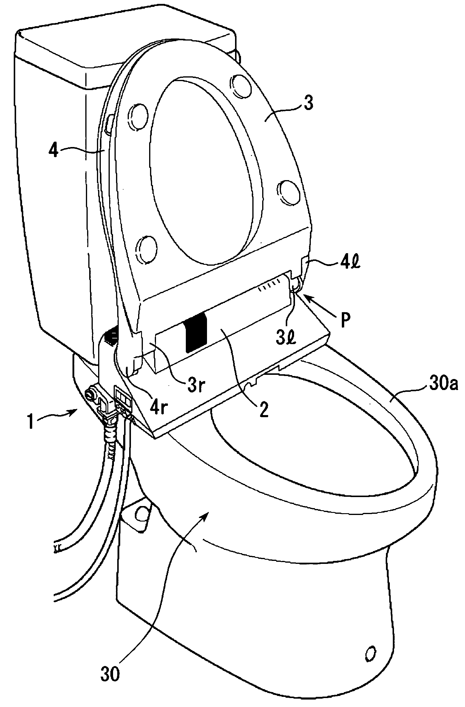
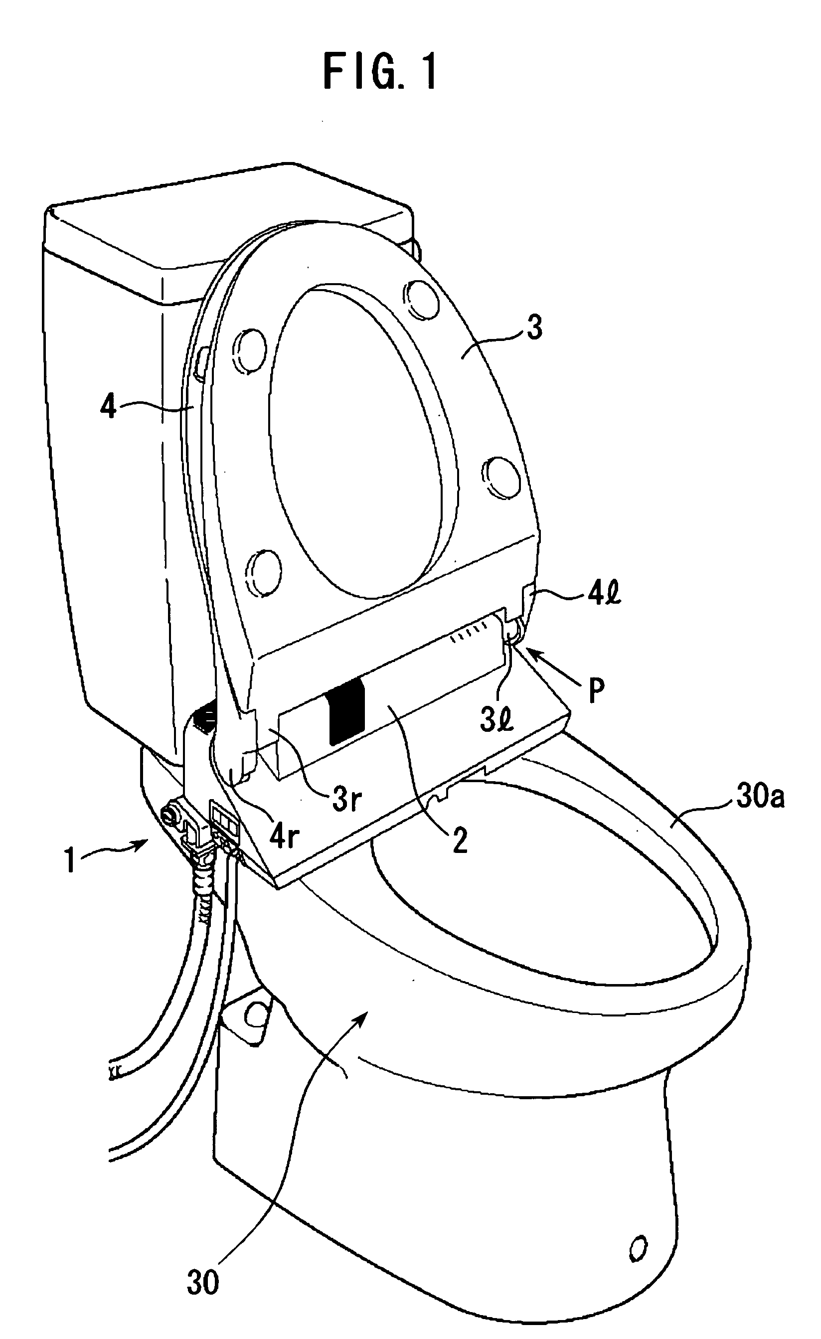
[0050] Referring to FIG. 1, a warm-water cleansing toilet seat device 1 is attached to a toilet bowl main body 30, in such a manner that a container case 2 for composing the device 1 is fixed on the top face of a rim 30a on the back side of the toilet bowl main body 30. A toilet seat 3 and a toilet cover 4 are attached to the container case 2 rotatably with respect to base end portions 3l, 3r, 4l, and 4r, respectively. The base end portions 3l, 3r, 4l, and 4r of the toilet seat 3 and the toilet cover 4 can be separated from the container case 2 by a mechanism, which will be described later.

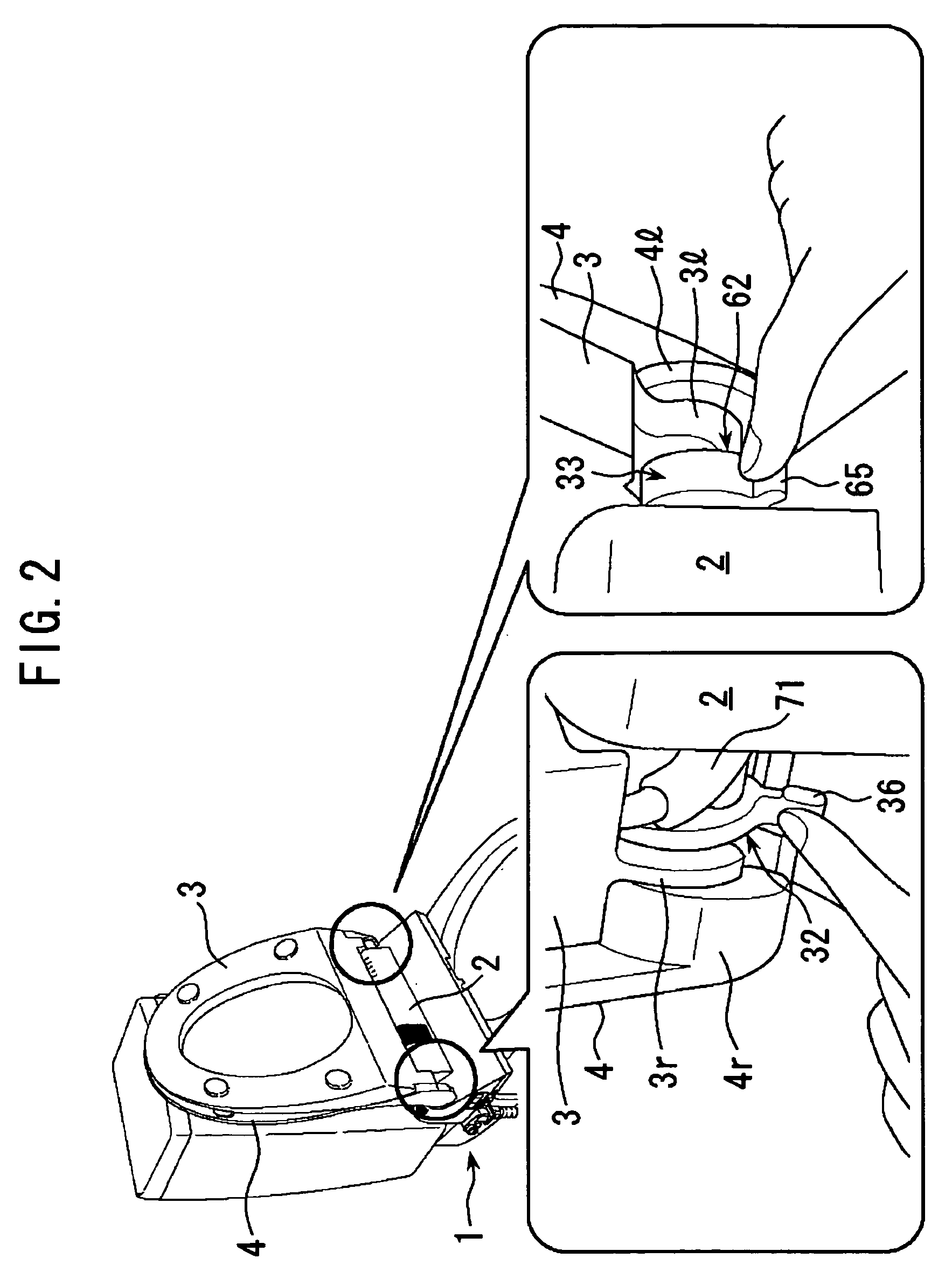
[0051] When the toilet cover 4 and the toilet seat 3 are in a lifted state (raised state), as shown in FIG. 2, a lever section 36 of a first engagement member 32 and a cord 71 are visible between the base end portion 3r on the left side of the toilet seat 3 and the container case 2. A lever section 65 of a lock section 6...

second embodiment

[0088] Next, a transmission unit according to the present invention will be described with reference to FIG. 23. The same reference numbers refer to parts which have the same function and effect as those of the structural parts of the foregoing toilet seat transmission unit 9.

[0089] A toilet seat transmission unit 29 according to this embodiment comprises a container cylinder 11, a swing shaft 12, torsion springs 13a and 13b, and a container cover 14. One end of the torsion spring 13a is inserted into an attachment hole 11c, so that the torsion spring 13a is fixed to the container cylinder 11. The other end of the torsion spring 13a is inserted into an attachment hole 12e, so that the torsion spring 13a is fixed to the swing shaft 12. One end of the torsion spring 13b is inserted into an attachment hole 11d, so that the torsion spring 13b is fixed to the container cylinder 11. The other end of the torsion spring 13b is inserted into an attachment hole 12d, so that the torsion spring...

third embodiment

[0092] Next, a transmission unit according to the present invention will be described with reference to FIG. 24. The same reference numbers refer to parts which have the same function and effect as those of the structural parts of the foregoing toilet seat transmission unit 9.

[0093] A toilet seat transmission unit 39 according to this embodiment comprises a container cylinder 11, a swing shaft 12, torsion springs 13c and 13d, an intermediate swing shaft 23, and a container cover 14. One end of the torsion spring 13c is inserted into an attachment hole 11c, so that the torsion spring 13c is fixed to the container cylinder 11. The other end of the torsion spring 13c is inserted into an attachment hole 23a, so that the torsion spring 13c is fixed to the intermediate swing shaft 23. One end of the torsion spring 13d is inserted into an attachment hole 23b, so that the torsion spring 13d is fixed to the intermediate swing shaft 23. The other end of the torsion spring 13d is inserted into...


PUM


Abstract

A lifting and lowering device (31) for a toilet seat or a toilet cover has a swing shaft (17) provided on a swing center line (C) of a toilet seat (3) or a toilet cover (4) that swings around base end portions (3l, 4l), respectively, and rises. The device comprises a lifting and lowering control unit (5) indirectly fixed to a toilet bowl main body (30); an output shaft (12) that is provided on the swing center line (C), one end portion of which shaft being removably connected to the swing shaft (17) of the lifting and lowering control unit (5) and the other end portion being detacheably connected to the base end portion (3l) of the toilet seat (3); and a toilet seat transmission unit (9) containing a tortion spring (13) that urges the output shaft (12) in a lifting direction of the toilet seat (3). The lifting and lowering device (31) for the toilet seat of toilet cover is relatively small in size and able to stabely hold the toilet seat or toilet cover in a raised position. Commonality of structural parts can be achieved depending on the magunitude of torque caused by the self weight of the toilet seat or toilet cover.

Description

TECHNICAL FIELD [0001] The present invention relates to a lifting and lowering device for a toilet seat or toilet cover provided in a Western-style toilet, and a transmission unit for composing the lifting and lowering device. BACKGROUND ART [0002] A conventional Western-style toilet had simple structure, in which a toilet seat and a toilet cover were pivotally supported so as to rise and fall on the top face of a rim on the back side of a toilet bowl main body. In recent years, however, a toilet seat device with function of cleansing the bottom with warm water or a heated toilet seat device has been installed in the toilet. In such a toilet, the toilet seat and the toilet cover are pivotally supported by a container case, which is disposed in the top surface of the rim. As the container case contains electrical components and the like for operating and controlling the cleansing function with warm water and the function of heating the toilet seat, the container necessarily protrudes...

Claims


Application Information

Patent Timeline
IPC IPC(8): A47K13/10A47K13/12
CPCA47K13/12A47K13/10
Inventor HAYASHI, RYOSUKETERADA, YOSHIROKATO, SATOSHIHASHIDUME, KENJI
Owner TOTO LTD
Why Eureka
Try Eureka