MOCVD apparatus and MOCVD method

a mocvd and apparatus technology, applied in the direction of coatings, chemical vapor deposition coatings, metallic material coating processes, etc., can solve the problems of inability to significantly obtain thin films having satisfactory quality, decreased temperature may not form thin films having satisfactory properties on the substrate, etc., to achieve the effect of suppressing the temperature decrease of the source gas, reducing the volume of the gas passage, and reducing the temperature of the source gas

Inactive Publication Date: 2005-08-11
SEIKO EPSON CORP +1
View PDF4 Cites 298 Cited by
  • Summary
  • Abstract
  • Description
  • Claims
  • Application Information

AI Technical Summary

Benefits of technology

[0009] According to the MOCVD apparatus just mentioned above, the adiabatic expansion of the source gas can be suppressed to thereby effectively suppress the temperature decrease of the source gas due to adiabatic expansion by reducing the volume of the gas passage in the deposition chamber. A thin film having satisfactory properties can thereby be formed.
[0010] In the MOCVD apparatus according to the present invention, it is acceptable that the supply mechanism includes an MO source container housing the MO source, a fir

Problems solved by technology

Such a source gas having a decreased temperature may not form a thin film having satisfactory proper

Method used


Image

  • MOCVD apparatus and MOCVD method
  • MOCVD apparatus and MOCVD method
  • MOCVD apparatus and MOCVD method

Examples


first embodiment

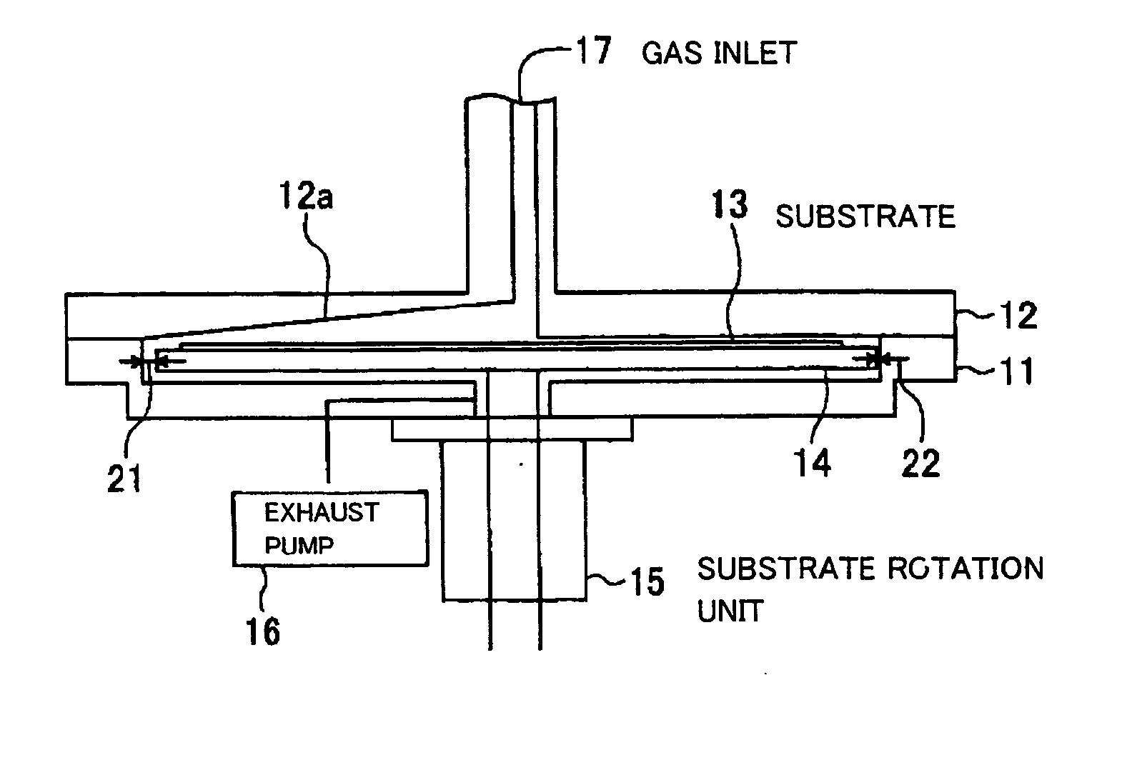
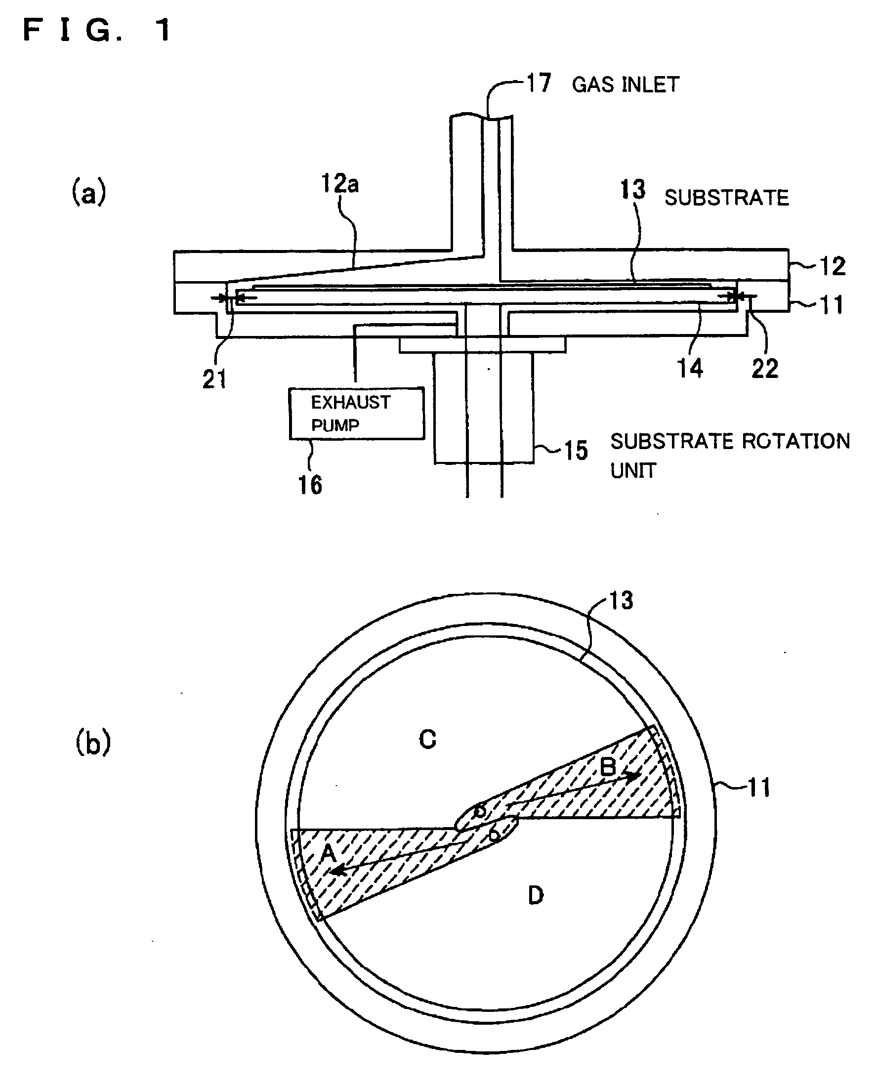
[0020]FIG. 1(a) is a sectional view of a schematic configuration of an MOCVD apparatus as the present invention, and FIG. 1(b) is a top view of the MOCVD apparatus shown in FIG. 1(a).

[0021] FIGS. 1(a) and 1(b) show that the MOCVD apparatus comprises a deposition chamber which comprises a lower chamber 11 and an upper chamber 12. By connecting the lower chamber 11 with the upper chamber 12, an inner space of the chamber is formed as shown in FIG. 1(a). A rotary substrate holder 14 for holding a substrate 13 is arranged in an inner space of the lower chamber 11. The substrate holder 14 has a rotation axis which is inserted into a substrate rotation unit 15. The substrate rotation unit 15 rotates the rotation axis to thereby rotate the substrate holder 14. An exhaust pump 16 is arranged in the vicinity of the lower chamber 11. The exhaust pump 16 serves to exhaust raw materials after deposition and other substances from under the substrate holder 14.

[0022] A deposition plane of the su...

second embodiment

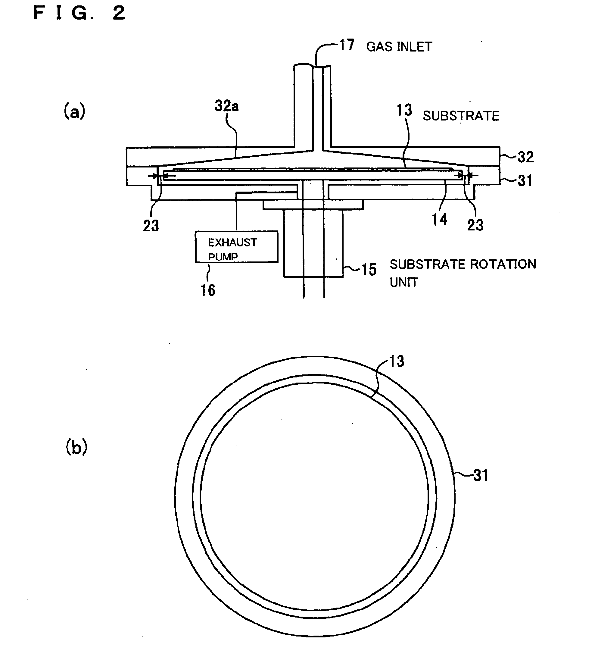
[0045]FIG. 2(a) is a sectional view of a schematic configuration of an MOCVD apparatus according to the present invention, and FIG. 2(b) is a top view of the MOCVD apparatus shown in FIG. 2(a), in which the same components as in FIG. 1 have the same reference numerals, and description thereof will be omitted as long as possible.

[0046] FIGS. 2(a) and 2(b) show that the MOCVD apparatus comprises a deposition chamber which comprises a lower chamber 31 and an upper chamber 32. By connecting the lower chamber 31 with the upper chamber 32, an inner space of the chamber is formed as shown in FIG. 2(a). A rotary substrate holder 14 for holding a substrate 13 is arranged in an inner space of the lower chamber 31.

[0047] A deposition plane of the substrate 13 on which a film is deposited in the deposition chamber is the entire surface of the substrate as shown in FIG. 2(b). The upper chamber 32 locating above the substrate has an umbrella-like sectional shape having a slope 32a as shown in FI...


PUM

PropertyMeasurementUnit
Temperatureaaaaaaaaaa
Areaaaaaaaaaaa

Abstract

[Object] To provide an MOCVD apparatus and a MOCVD method which can deposit a thin film having satisfactory properties by preventing temperature decrease of a source gas.
[Solving Means] An MOCVD apparatus according to the present invention is an apparatus for supplying a source gas as a mixture of an MO source gas with an oxidizing gas to a substrate 13 to thereby form a film. The MOCVD apparatus includes a substrate holder 14 for holding the substrate 13; a deposition chamber for housing the substrate holder; a supply mechanism for supplying the source gas to a surface of the substrate; and a heating device for heating the substrate 13 held by the substrate holder. The deposition chamber includes a substrate housing unit for housing the substrate holder holding the substrate, and a passage housing unit being connected to the substrate housing unit and constituting a passage for supplying the source gas to the substrate. The passage has a cross-sectional area smaller than the area of a deposition plane of the substrate 13 when the passage housing unit is cut in parallel with the deposition plane of the substrate 13.

Description

TECHNICAL FIELD [0001] The present invention relates to MOCVD apparatus and method in which a source gas as a mixture of an MO source gas with an oxidizing gas is supplied to thereby form films. BACKGROUND ART [0002] Conventional MOCVD (metal organic chemical vapor deposition) apparatus are CVD apparatus using an organometallic compound as a source or raw material and generally use powders or other raw materials which are solid or liquid at normal pressure and temperature. In these MOCVD apparatus, such a raw material is provided in a container, is heated under reduced pressure and is thereby vaporized. The vaporized gaseous material is transmitted with a carrier gas toward a deposition chamber. A passage through which the source gas flows is thereby always heated. In addition, oxygen gas is supplied to the passage of the source gas. Then, a gaseous mixture of the source gas and oxygen gas is supplied into the deposition chamber. The material used in MOCVD remains gaseous before rea...

Claims


Application Information

Patent Timeline
IPC IPC(8): C23C16/00C23C16/44C23C16/455
CPCC23C16/45508C23C16/455
Inventor KIJIMA, TAKESHINATORI, EIJISUZUKI, MITSUHIRO
Owner SEIKO EPSON CORP
Why Eureka
Try Eureka