Heat pump system

a heat pump and heating medium technology, applied in heat pumps, lighting and heating apparatus, refrigeration components, etc., can solve the problems of insufficient heating capacity of blown air, inability to perform stable defrosting, etc., to suppress the temperature decrease of heat medium, stable defrosting capacity, and suppress the effect of heating capacity decreas

Active Publication Date: 2019-01-31
DENSO CORP
View PDF2 Cites 30 Cited by
  • Summary
  • Abstract
  • Description
  • Claims
  • Application Information

AI Technical Summary

Benefits of technology

[0010]According to this, since the throttle opening degree controller increases the opening degree of the decompressor, the defrosting of the outside heat exchanger can be performed by increasing the temperature of the refrigerant flowing into the outside heat exchanger.
[0011]At this time, since the pumping capacity controller increases the pumping capacity with increase of the required heating capacity, it is possible to prevent the refrigerant from dissipating heat required for defrosting by the first heat exchanger. Further, it is possible to suppress the temperature decrease of the heat medium flowing out of the first heat exchanger and to supply the heat medium at a relatively high temperature to the second heat exchanger.
[0012]That is, according to this aspect, it is possible to provide a heat pump system capable of suppressing a decrease in heating capacity for heating heating target fluid while exhibiting a stable defrosting capacity during a defrosting operation.

Problems solved by technology

According to study of the inventor of the present disclosure, in the heat pump system of the Patent Document 1, a defrosting capacity for defrosting the outside heat exchanger is changed when the temperature of the hot water changes, and accordingly the heat pump system may not perform a stable defrosting.
Furthermore, if the temperature of the hot water is low, the heating capacity of the blown air may become insufficient.

Method used


Image

  • Heat pump system
  • Heat pump system
  • Heat pump system

Examples


first embodiment

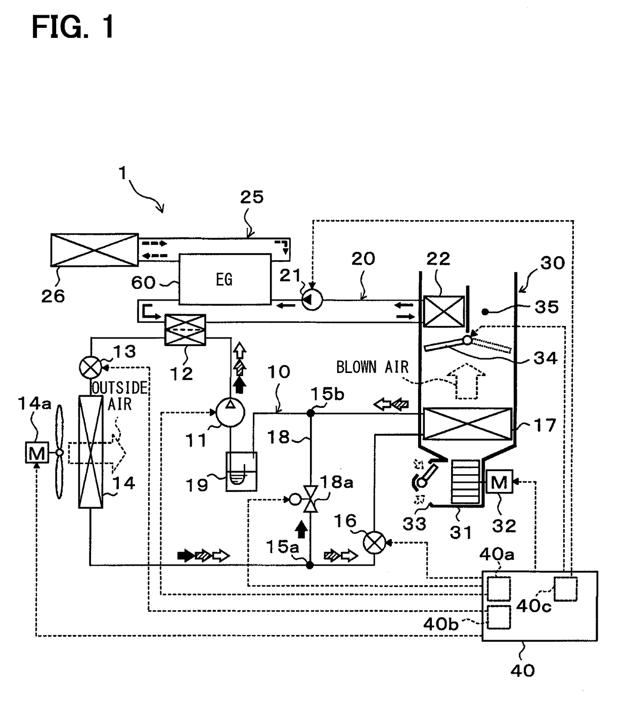
[0026]Hereinafter, a first embodiment of the present disclosure will be described with reference to FIGS. 1 to 7. In the present embodiment, a heat pump system 1 of the present disclosure is applied to an air-conditioning device for a hybrid vehicle which obtains a driving force for vehicle traveling from both of an internal combustion engine (engine) 60 and a traveling electric motor. The heat pump system 1 of an air-conditioner for vehicle performs a function of heating or cooling blown air blown into a vehicle compartment which is an air-conditioning target space.

[0027]The heat pump system 1 includes a heat pump cycle 10, which is a vapor compression type refrigeration cycle for heating or cooling the blown air, and a heat medium circulation circuit 20 in which cooling water of the engine 60 circulates. When the blown air is heated, the heat pump system 1 is capable of heating the cooling water by the heat pump cycle 10 and heating the blown air by using the heated cooling water ...

second embodiment

[0169]In the present embodiment, as shown in the overall configuration diagram of FIG. 8, an example in which a shutter 27 is added to the first embodiment will be described. In FIG. 8, the same reference numerals are assigned to the same or equivalent portions as those of the first embodiment. This also applies to the following drawings.

[0170]The shutter 27 opens and closes an inflow path of the outside air flowing into the radiator 26. As the shutter 27, one having multiple cantilevered plate doors and a servomotor for driving the plate doors can be adopted. The operation of the shutter 27 is controlled by a control signal output from the air-conditioning controller 40. Therefore, in the air-conditioning controller 40 of the present embodiment, the configuration for controlling the operation of the shutter 27 constitutes a heat radiation capacity control unit 40d.

[0171]The radiator 26 exchanges heat between the cooling water and the outside air to dissipate heat of the cooling wa...

third embodiment

[0177]In the present embodiment, as shown in the overall configuration diagram of FIG. 9, an example in which a water bypass passage 28 and three-way valve 28a are added to the first embodiment will be described.

[0178]The water bypass passage 28 is a cooling water pipe that guides the cooling water pumped from the water pump 21 to the three-way valve 28 to bypass the engine 60.

[0179]The three-way valve 28a is disposed on the outlet side of the water bypass passage 28. The three-way valve 28a is an electric three-way valve that switches between a heat medium circuit for guiding the cooling water flowing out of the water bypass passage 28 to the water passage inlet side of the water-refrigerant heat exchanger 12 and a heat medium circuit for guiding the cooling water circulating in the heat dissipation circulation circuit 25 to the water passage inlet side of the water-refrigerant heat exchanger 12.

[0180]The operation of the three-way valve 28a is controlled by a control voltage outpu...


PUM


Abstract

A heat pump system includes a heat pump cycle, a heat medium circulation circuit, and a refrigeration cycle device. The refrigeration cycle device is configured to perform a defrosting operation when a frost formation determiner determines that frost is formed. A throttle opening degree controller is configured to increase an opening degree in the defrosting operation. A pumping capacity controller is configured to increase a pumping capacity in the defrosting operation with increase of a required heating capacity required for heating a heating target fluid, the pumping capacity controller increasing the pumping capacity such that heat of refrigerant discharged from a compressor is transferred to heat medium in a first heat exchanger within a range in which a temperature of the refrigerant flowing into an outside heat exchanger is capable of melting the frost formed on the outside heat exchanger.

Description

CROSS REFERENCE TO RELATED APPLICATION[0001]This application is based on and incorporates herein by reference Japanese Patent Applications No. 2016-011531 filed on Jan. 25, 2016, and No. 2016-236054 filed on Dec. 5, 2016.TECHNICAL FIELD[0002]The present disclosure relates to a heat pump system that heats a heat medium by a heat pump cycle and heats a heating target fluid by using the heated heat medium as a heat source.BACKGROUND ART[0003]Conventionally, Patent Document 1 discloses a heat pump system which heats hot water that is a heat medium by a heat pump cycle (i.e. a vapor compression type refrigeration cycle) and exchanges heat between heated hot water and blown air that is a heating target fluid.[0004]The heat pump system of Patent Document 1 performs a defrosting operation to remove frost when frost is formed on an outside heat exchanger functioning as an evaporator of the heat pump cycle. Specifically, the heat pump system of Patent Document 1 performs a so-called hot-gas d...

Claims


Application Information

Patent Timeline
Patent Type & Authority Applications(United States)
IPC IPC(8): B60H1/22F25B47/02F24F11/84B60H1/32B60H1/00
CPCB60H1/22F25B47/02F24F11/84B60H1/321B60H1/00899B60H2001/00949B60H1/00921F25B5/04F25B30/02F25B40/04F25B2400/0409F25B2400/0411F25B2600/02F25B2600/13F25B2600/2501F25B2600/2513B60H2001/00961
Inventor TADA, KAZUHIRO
Owner DENSO CORP
Why Eureka
Try Eureka