Hydraulic brake actuator comprising electrically actuable lock for park brake

a technology of hydraulic brake actuator and park brake, which is applied in the direction of actuators, mechanically actuated brakes, brake types, etc., can solve the problems of actuator not being reliably engaged, hydraulic pressure is reduced, and the pedal, linkage and locking mechanism add significant cost and weight to the vehicle, so as to reduce the size and cost of the braking system, and ensure the reliability of the park brak

Active Publication Date: 2005-08-11
CHANGZHOU BWI AUTOMOTIVE ELECTRONIC TECH CO LTD +1
View PDF14 Cites 37 Cited by
  • Summary
  • Abstract
  • Description
  • Claims
  • Application Information

AI Technical Summary

Benefits of technology

[0009] By securing the wedge in the advanced position, the hydraulic piston is prevented from retracting and so locks the brake pads against the rotor with effective brake force to provide a reliable park brake. The hydraulic piston is locked in position without hydraulic pressure or electrical power, so that the park brake is reliable even after the vehicle is turned off. Moreover, this invention takes advantage of the hydraulic piston and other components already provided in common braking systems, and combines the functions for the park brake. Also, the invention allows the park brake to be electrically applied, by means of a switch and a connection to the vehicle electrical system, thereby eliminating the need for a cable linkage and a pedal mechanism. Still further, the electrical actuator is required only to advance the wedge and does not apply brake force. As a result, the size and cost of the braking system is reduced, without compromising the reliability of the park brake function.

Problems solved by technology

Moreover, the pedal, linkage and locking mechanism add significant cost and weight to the vehicle.
However, when the vehicle is not in operation, as when the park brake is needed, the hydraulic pressure is reduced, and the actuator may not be or remain reliably engaged.
However, in order to apply a force sufficient to clamp the brake pads against the rotor to prevent rolling of the vehicle, a relatively large electrical device is required.
These requirements increase the cost, size and complexity of an electromechanical park brake system.

Method used


Image

  • Hydraulic brake actuator comprising electrically actuable lock for park brake
  • Hydraulic brake actuator comprising electrically actuable lock for park brake
  • Hydraulic brake actuator comprising electrically actuable lock for park brake

Examples


Embodiment Construction

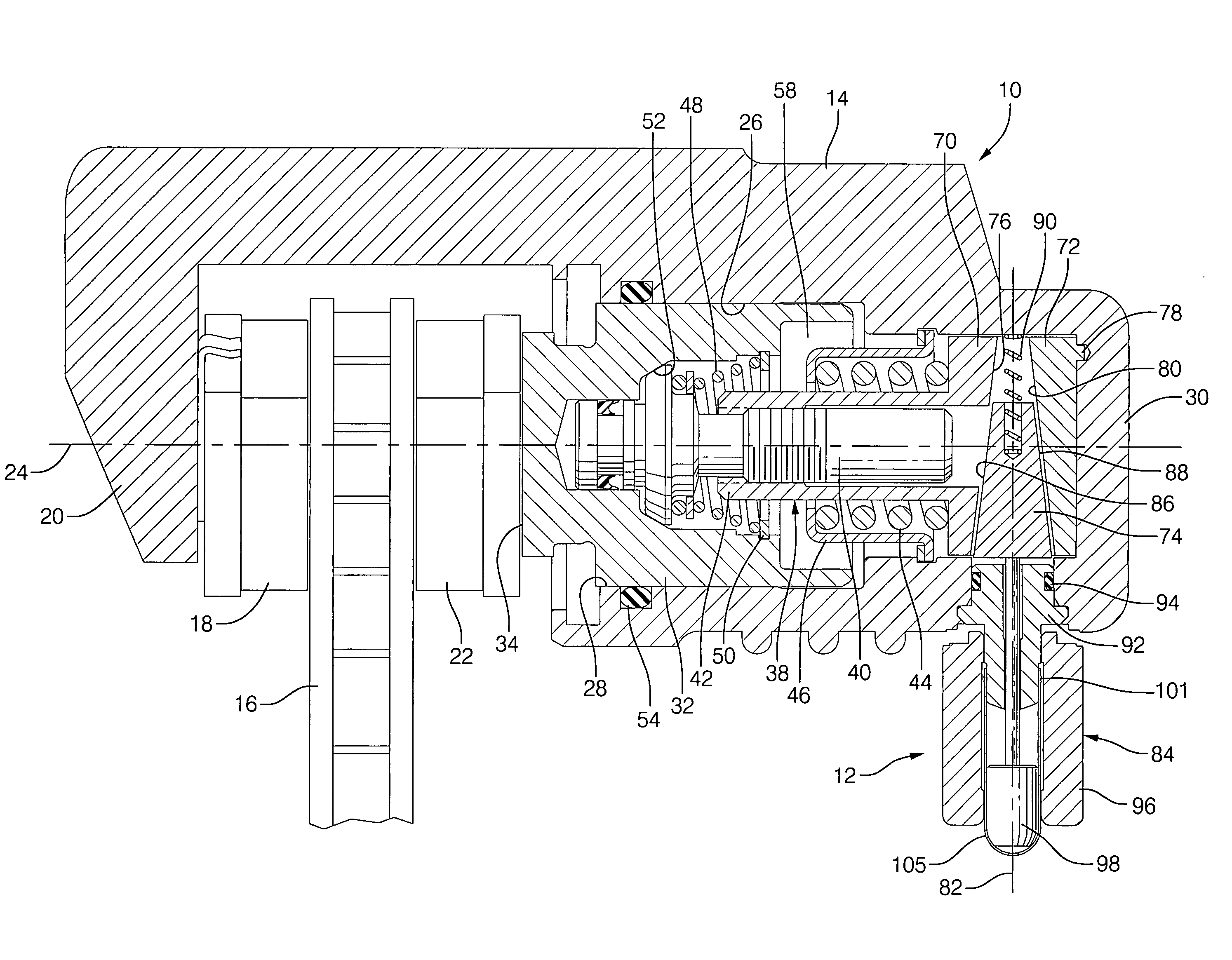
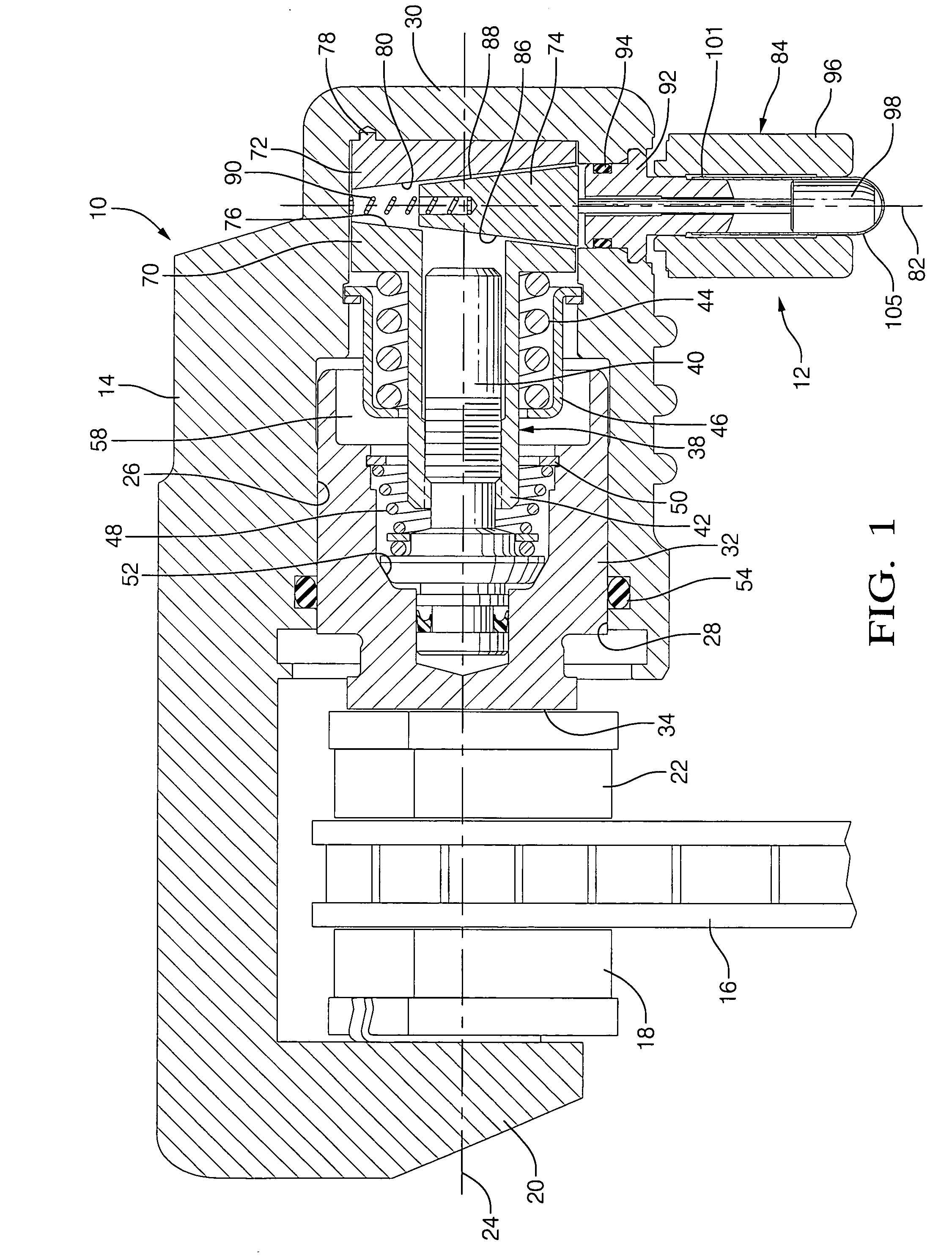
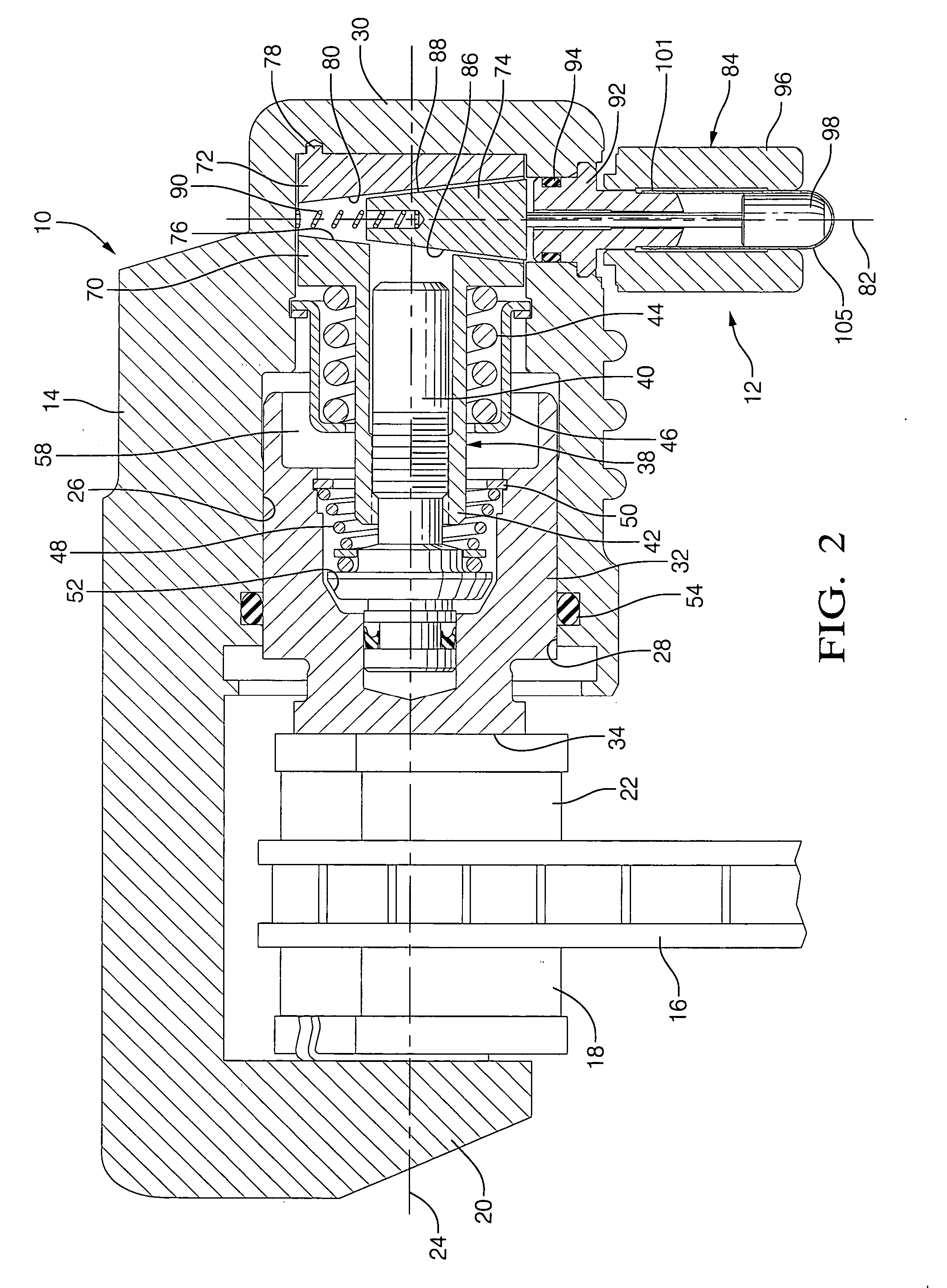
[0018] In accordance with a preferred embodiment of this invention, referring to FIGS. 1 through 4, a hydraulic brake actuator 10 having an electrically actuable lock assembly 12 is provided for a braking system of an automotive vehicle, wherein lock assembly 12 is adapted to lock actuator 10 when the vehicle is not in operation to secure the vehicle wheel and thereby provide a park brake. Actuator 10 comprises a metal caliper housing 14 that is mounted adjacent a wheel of the vehicle, preferably a rear wheel. To apply the brake, the actuator engages a rotor 16 mounted to the hub of the wheel and rotating therewith. The braking system is of the type referred to as a caliper assembly and includes an outer brake pad 18 mounted to a caliper arm 20 of housing 14 and an inner brake pad 22 that is mounted to the vehicle chassis opposite brake pad 18, such that pads 18 and 20 are disposed about rotor 16 and move along an axis 24 in opposed directions to apply or release the brake, in a con...


PUM


Abstract

In an automotive vehicle braking system, a hydraulic brake actuator includes a wedge for locking a hydraulic piston in a brake position for purposes of applying a park brake. To apply the park brake, hydraulic pressure is increased to advance the piston to urge the brake pads against the rotor. With the piston in the brake position, an electrical solenoid is energized to advance the wedge to engage the piston. The wedge includes an inclined surface that contacts an inclined surface connected to the piston or the housing, with sufficient frictional force to maintain the wedge in the advanced position without requiring hydraulic pressure or electrical power. Thus, the park brake remains applied even when the vehicle is turned off.

Description

CROSS REFERENCE TO RELATED APPLICATION [0001] This application claims the benefit of U.S. Provisional Application No. 60 / 542,909, filed Feb. 9, 2004, which is incorporated herein by reference.TECHNICAL FIELD OF INVENTION [0002] This invention relates to a hydraulic brake actuator for an automotive vehicle. More particularly, this invention relates to such hydraulic brake actuator that includes a wedge operated by a solenoid or the like to lock the actuator for purposes of providing a park brake. BACKGROUND OF INVENTION [0003] In a typical automotive vehicle, a brake system includes brake pads disposed about a rotor mechanically coupled to a wheel and operated by a caliper assembly. During vehicle travel, the brake pads are spaced apart from the rotor to allow free rotation of the rotor, and thus the wheel. When stopping is desired, the caliper assembly clamps the brake pads against the rotor, creating friction that inhibits rotation of the rotor. In a conventional brake system, the ...

Claims


Application Information

Patent Timeline
Patent Type & Authority Applications(United States)
IPC IPC(8): F16D55/08F16D65/28F16D65/14
CPCF16D65/18F16D2121/02F16D2129/08F16D2127/06F16D2125/66
Inventor REUTER, DAVID F.FULKS, GARY C.
Owner CHANGZHOU BWI AUTOMOTIVE ELECTRONIC TECH CO LTD
Why Eureka
Try Eureka