
Paper tag identified by using radiofrequency and method of manufacturing the same

a radiofrequency identification and paper tag technology, applied in the field of paperlike rfid (radiofrequency identification) tags, can solve the problems of large rollover load, chip damage, and large deterioration of the smooth surface of the rfid tag in comparison with the ordinary type of paper, and achieve high quality, high quality, and feed stably

Inactive Publication Date: 2005-08-11
HITACHI LTD
View PDF7 Cites 18 Cited by
  • Summary
  • Abstract
  • Description
  • Claims
  • Application Information

AI Technical Summary

Benefits of technology

[0011] It is an object of the present invention to solve the above-mentioned problems and provide a paper-like RFID tag of high quality having a thickness of about 0.1 mm or less, having a surface smoothness approximately equal to that of the ordinary type of paper, and having a long communication distance not limited by the profile size of an RFID chip.
[0012] It is another object of the present invention to provide a method capable of manufacturing the aforesaid paper-like RFID tag of high quality.
[0025] According to the present invention, a paper-like RFID tag of high quality capable of performing a long-distance communication and having a smooth and thin paper surface with a thickness of about 0.1 mm or less can be fed stably.
[0026] According to the present invention, a paper-like RFID tag of high quality capable of performing a long-distance communication and having a smooth and thin paper surface with a thickness of about 0.1 mm or less can be manufactured.

Problems solved by technology

In the paper making process, pressurization, heating, and dewatering, are performed using a large number of rollers in order to ensure smoothness of the paper surface, but in these processes the roller load is very large.
If such a very large load is imposed on the RFID chip inlaid between paper layers, the chip will be destroyed.
If the roller load is greatly weakened in an effort to solve this problem, the smoothness of the surface of the RFID tag will be greatly deteriorated in comparison with the ordinary type of paper.

Method used


Image

  • Paper tag identified by using radiofrequency and method of manufacturing the same
  • Paper tag identified by using radiofrequency and method of manufacturing the same
  • Paper tag identified by using radiofrequency and method of manufacturing the same

Examples


Embodiment Construction

[0042] With reference to the drawings, the present invention will be described hereinunder by way of embodiments thereof which are preferred for manufacturing paper-like RFID tags related to the present invention.

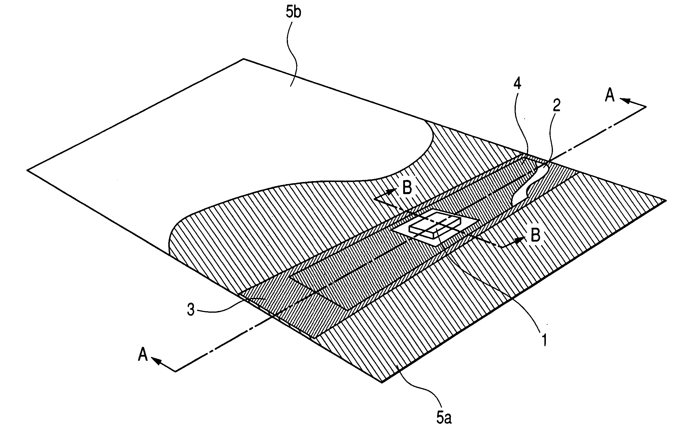
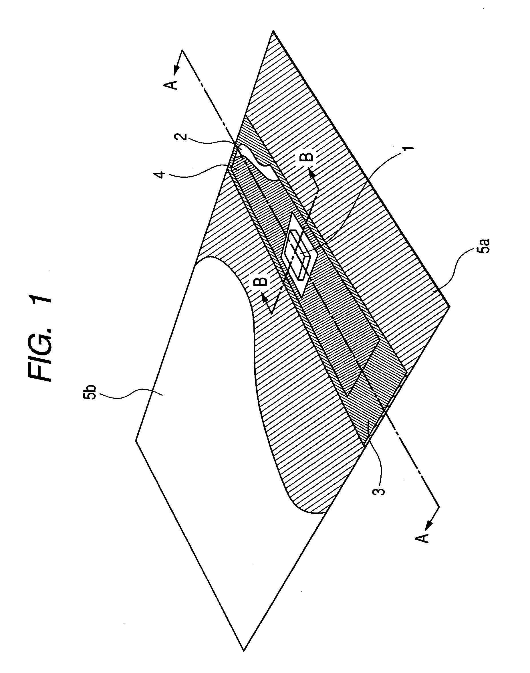
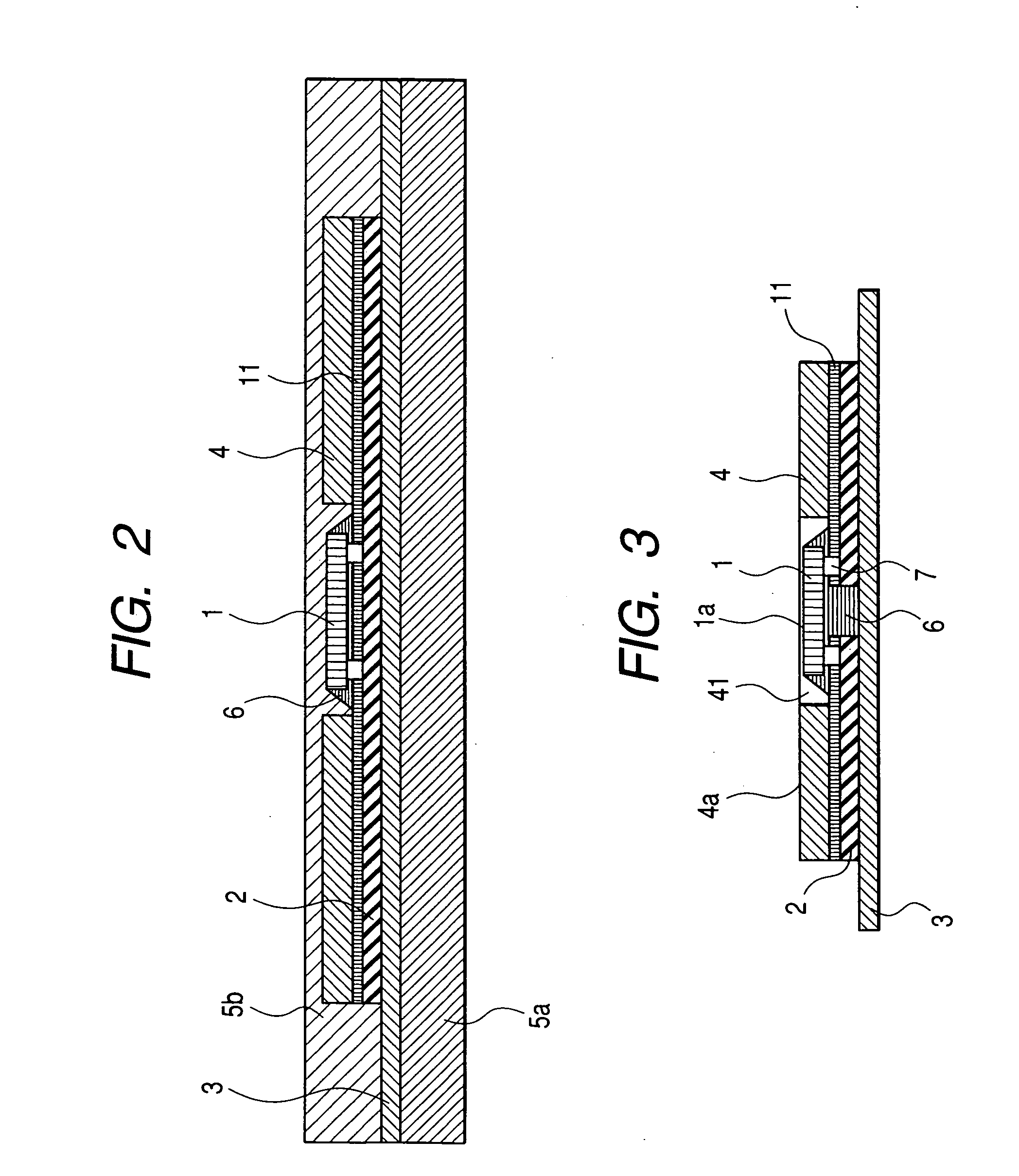
[0043] First, a description will be given about the construction of a paper-like RFID tag according to a first embodiment of the present invention. FIG. 1 is a partially cut-away perspective view of the paper-like RFID tag of the first embodiment, FIG. 2 is a sectional view as seen in the direction of arrow A-A in FIG. 1, and FIG. 3 is a sectional view as seen in the direction of arrow B-B in FIG. 1. In FIG. 3, a bonded portion between an RFID chip 1 and an antenna 2 is shown in detail and a first paper layer 5a and a second paper layer 5b, which are shown in FIGS. 1 and 2, are omitted.

[0044] The paper-like RFID tag of this first embodiment comprises an RFID chip 1 having memory for storing identification data (ID data) and other information, an antenna 2 formed by patter...


PUM


Abstract

A paper-like RFID tag is fabricated by bonding bumps of an RFID chip to an antenna to connect the chip to the antenna, the antenna being formed by a metal foil bonded onto a base film or a base tape, providing a protecting material around the RFID chip so that an upper surface becomes higher than that of the RFID chip, to constitute an RFID thread, and inlaying the RFID thread in between first and second paper layers to afford a paper-like structure. The thickness of the paper-like RFID tag fabricated as above is 0.1 mm or less. Further, the paper-like RFID tag is of high quality and has a surface smoothness almost equal to that of the ordinary type of paper, permitting a long-distance communication.

Description

BACKGROUND OF THE INVENTION [0001] The present invention relates to a paper-like RFID (radiofrequency identification) tag with an RFID thread inlaid between paper layers, the RFID thread comprising an RFID chip and an antenna coupled together electrically, the RFID chip having identification data (ID data) stored in memory, as well as a method of manufacturing the same. [0002] Conventional ID card manufacturing methods are known in Japanese Patent Laid-Open Nos. Hei 11-150133 (Patent Document 1) and 2000-315697 (Patent Document 2). In Patent Documents 1 and 2 it is described that a film formed with wiring patterns and an antenna coil and with a thin IC chip mounted thereon, as well as an adhesive-laminated cover film, are inlaid between a pair of heated rolls and are laminated by the pair of heated rolls to fabricate an IC card. [0003] A method of making paper or a film-like tag is known in International Publication No. WO 00 / 36555 (Patent Document 3). In Patent Document 3 it is des...

Claims


Application Information

Patent Timeline
Patent Type & Authority Applications(United States)
IPC IPC(8): B42D15/10G06K19/07G06K19/077
CPCG06K19/07728G06K19/07749G06K19/0775H01L2224/16H01L2224/16225H01L2924/01079H01L2224/16227H01L2224/81395H01L2924/01057G06K19/07
Inventor INOUE, KOSUKEKANDA, NAOYAHONMA, HIROSHI
Owner HITACHI LTD
Learn More