Arrangement structure of speed-change cable

a technology of arrangement structure and speed-change cable, which is applied in the direction of article supporting device, transportation and packaging, cycle equipment, etc., can solve the problems of increasing the operating load of the derailleur, affecting the smooth operation of the derailleur, and the existence of the curved portion cannot be avoided in the extension forwardly of the vehicle body, so as to reduce the length of the cable, reduce the operating load, and reduce the slack of the speed-change cable

Inactive Publication Date: 2005-08-11
HONDA MOTOR CO LTD
View PDF7 Cites 8 Cited by
  • Summary
  • Abstract
  • Description
  • Claims
  • Application Information

AI Technical Summary

Benefits of technology

[0012] In the present invention, a structure is provided including a primary frame of a vehicle body extending obliquely rearwardly and downwardly from a head pipe which rotatably supports a handle. A transmission case is supported by the primary frame and accommodates the transmission in the internal space thereof. The transmission case includes a through-hole at a portion facing forwardly or upwardly of the vehicle body with a speed-change cable for causing the transmission to change the speed that passes through the through-hole. Therefore, since the speed-change cable is directed toward the head pipe, slack of the speed-change cable is reduced, whereby the operating load during a speed-change operation is reduced. Since there is little slack on the cable, the length of the cable can be reduced, whereby the cost and the weight can be reduced. In addition, since there is a large space around the through-hole, maintenance in the periphery of the through-hole can be easily performed.
[0013] In the present invention, the primary frame of the vehicle body includes a mainframe and a down tube extending from the head pipe rearwardly and downwardly substantially in parallel. The transmission case is disposed so as to overlap with at least part of the mainframe and the down tube in a side view with the through-hole being provided at substantially the same distance from the mainframe and the down tube. Therefore, the speed-change cable extends along the front portion of the vehicle body in a state of being substantially straight without a forcedly formed curved portion toward a speed-change operation member installed on the handle. Thus, generation of friction between a wire, which is an inner cable, and an outer tube, which is an outer cable is reduced to the minimum, and the reduction of speed-change load during speed-change operation is achieved, whereby the operability is improved. Also, reduction of the speed-change cable is achieved.
[0014] In the present invention, the transmission is provided with a gear shift mechanism (M2) for changing the speed by the operation of the speed-change cable, and the gear shift mechanism is disposed in front or above the transmission case. Therefore, since the length of the speed-change cable (wire) in the transmission case can be reduced within the transmission case by arranging the gear shift mechanism in front of or above the transmission case, the speed-change load can further be reduced. Thus, the cost and weight can further be reduced.

Problems solved by technology

Consequently, an operating load in operating the derailleur increases, and the smooth operability thereof is impaired.
Because of the arrangement structure of the above-described operating cable, the existence of the curved portion cannot be avoided in the extension forwardly of the vehicle body.
Thus, a reduction of the operating load for the speed-change is difficult due to its structure, and the securement of good operability is limited.
There is also a problem that a reduction in the length of the operating cable cannot be achieved.

Method used


Image

  • Arrangement structure of speed-change cable
  • Arrangement structure of speed-change cable
  • Arrangement structure of speed-change cable

Examples


Embodiment Construction

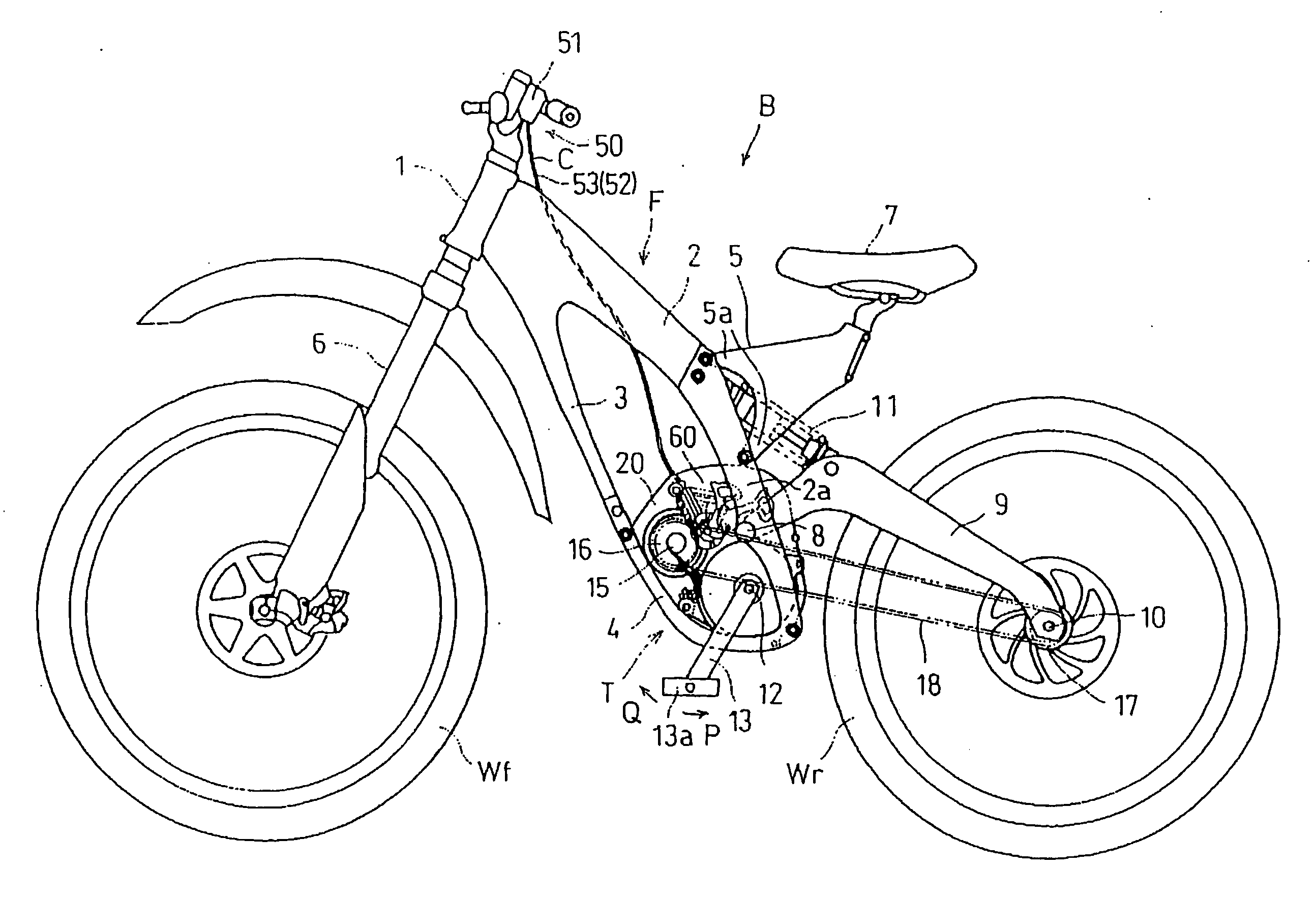
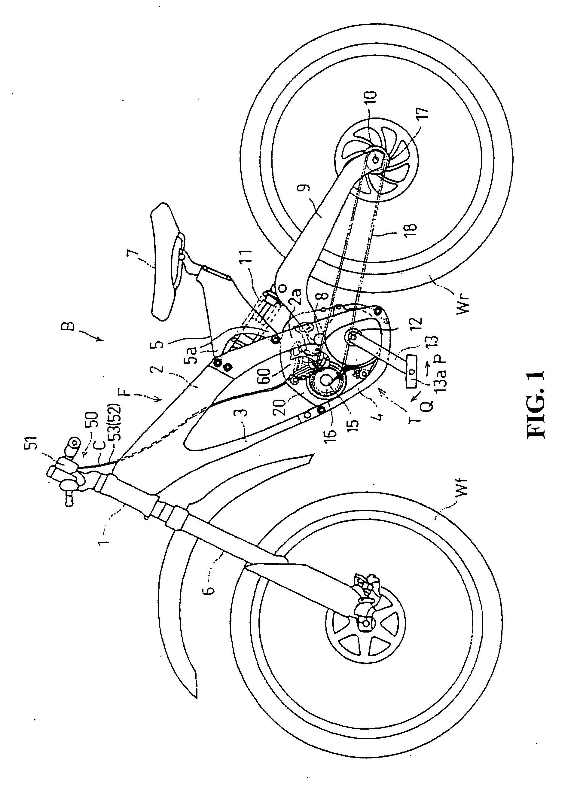
[0037] Referring now to FIG. 1 to FIG. 19, an embodiment of the structure of a transmission for a bicycle provided with a derailleur having a speed-change cable according to the present invention will be described.

[0038]FIG. 1 shows a left side view of a bicycle B using a transmission T provided with a derailleur according to the present invention.

[0039] The bicycle B is a downhill bicycle and is used for a competitive sport for competing against time for operating down a dirt course such as a forest road provided with a high-speed corner or a jumping section.

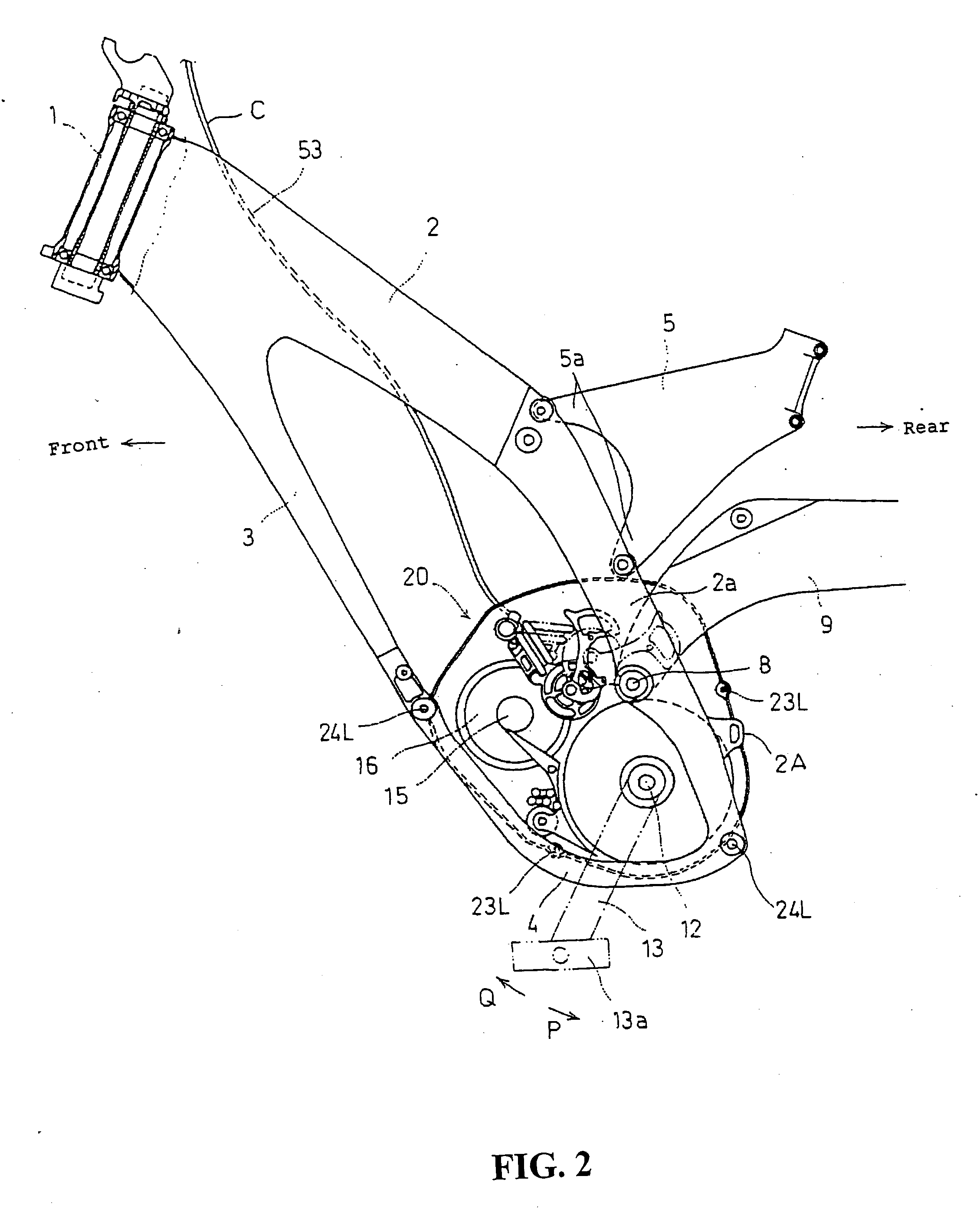
[0040] A vehicle body frame F of the bicycle B includes, as shown in FIGS. 1 and 2, a pair of left and right mainframes 2 extending from a head pipe 1 rearwardly and obliquely downward, and a down tube 3 extending from the front ends of both mainframes 2 rearwardly and obliquely downwardly at the lower portion thereof, and the lower ends of a pair of the mainframes 2 and the lower end of the down tube 3 are connected to each...


PUM


Abstract

To improve the operability by a speed-change cable and to reduce the cable by selecting an adequate arrangement structure of the speed-change cable from a transmission case to an operating element of a handle on the front portion of a vehicle body. An arrangement structure of a speed-change cable is such that the speed-change cable is attached at one end to an arm portion of a derailleur and the speed-change cable is guided from the mounting portion through an outer cable mounting hole of a derailleur shaft to a through-hole opening at the upper front portion of a transmission case, and extends from the through-hole outside the case and along the front frame of the vehicle body substantially straight. The extended end is attached to a cable operation mechanism at the handle on the front portion of the vehicle body.

Description

CROSS-REFERENCE TO RELATED APPLICATIONS [0001] The present application claims priority under 35 USC 119 to Japanese Patent Application No. 2004-034314 filed on Feb. 10, 2004 the entire contents of which are hereby incorporated by reference.BACKGROUND OF THE INVENTION [0002] 1. Field of the Invention [0003] The present invention relates to an arrangement structure of a speed-change cable. More specifically, to an arrangement structure of a speed-change cable in a transmission for a bicycle. [0004] 2. Description of Background Art [0005] A connecting portion of the speed-change cable connected to a derailleur in the transmission for a bicycle in the related art is located at the rear portion of the bicycle because the position to arrange the derailleur is in the vicinity of an axle of a rear wheel. Thus, the speed-change cable to be connected to the derailleur is arranged so as to extend from the connecting portion towards the rear of the vehicle body, inverted to form a curved portio...

Claims


Application Information

Patent Timeline
Patent Type & Authority Applications(United States)
IPC IPC(8): B62M25/02B62M1/36B62M11/14F16H61/36
CPCB62M11/145B62J11/13
Inventor MATSUMOTO, SHINYAINOUE, NAOKI
Owner HONDA MOTOR CO LTD
Why Eureka
Try Eureka