Imaging apparatus, phase control method, and synchronization method

a technology of synchronization and synchronization, applied in the field of synchronization methods, can solve the problems of time-consuming installation, degraded, and difficult to clearly display video on a monitor distant from the camera or the camera

Active Publication Date: 2005-08-11
SONY CORP
View PDF14 Cites 18 Cited by
  • Summary
  • Abstract
  • Description
  • Claims
  • Application Information

AI Technical Summary

Benefits of technology

[0010] The video synchronization signal may be a horizontal synchronization signal. Thus, it is only required to control one video synchronization signal so that no phase difference occurs, leading to high-efficiency phase synchronization control.
[0011] The connection cable may be an optical fiber cable. This allows a video signal, etc., to be transmitted at high rate between the camera device and the signal processor that are distant from each other.
[0014] The phase of the synchronization signal may be synchronized with the phase of an external synchronization signal transmitted from an external device. Thus, control from the external device, such as switching of video, can be performed timely.
[0015] The second phase controller may output a second transmission synchronization signal whose phase is synchronized with the phase of an external synchronization signal transmitted from an external device. Since the phase of the second transmission signal is synchronized with the phase of the video signal, an instruction signal from the signal processor can be switched timely according to the phase of the video signal.
[0019] According to the present invention, the synchronization determining units of the camera device and the signal processor allow synchronization to be established from the camera device to the signal processor and from the signal processor to the camera device. Thus, synchronization is automatically established between the camera device and the signal processor without any special synchronization processing.
[0028] According to the present invention, therefore, in an imaging apparatus including an optical fiber cable, synchronization can be established, thus allowing a high-quality video signal to be transmitted to a distant place.

Problems solved by technology

In the imaging apparatus, the network is established using a multi-core cable, which requires time-consuming installation because of its complicated connection, and the multi-core cable typically carries analog signals.
Video signals transmitted over a long distance can become degraded, thus making it difficult to clearly display video on a monitor distant from the camera or cameras.

Method used


Image

  • Imaging apparatus, phase control method, and synchronization method
  • Imaging apparatus, phase control method, and synchronization method
  • Imaging apparatus, phase control method, and synchronization method

Examples


Embodiment Construction

[0041] Preferred embodiments of the present invention will now be described in detail with reference to the accompanying drawings. In the following description and throughout the accompanying drawings, components having substantially the same function and structure are given the same reference numerals, and a redundant description thereof is thus omitted.

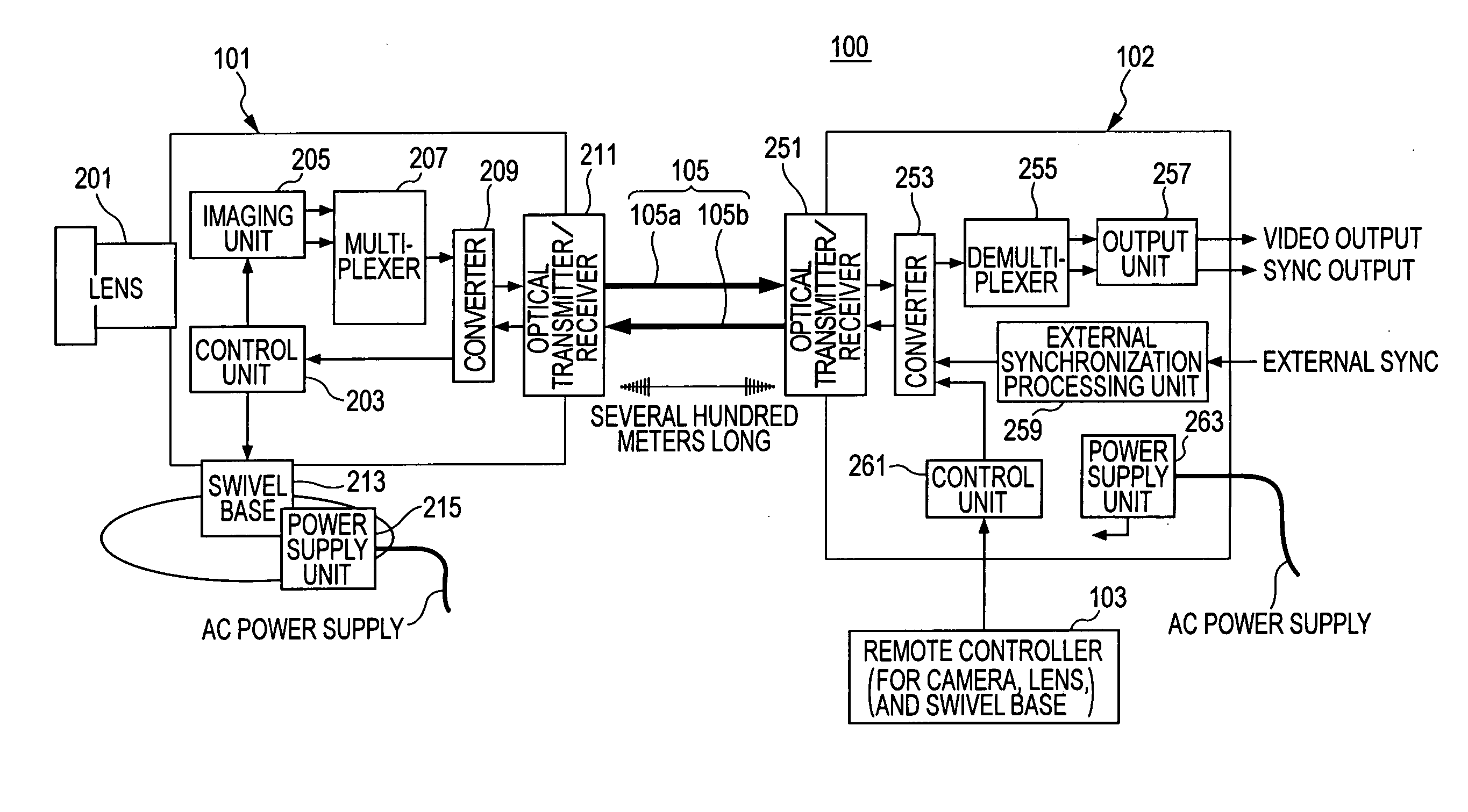
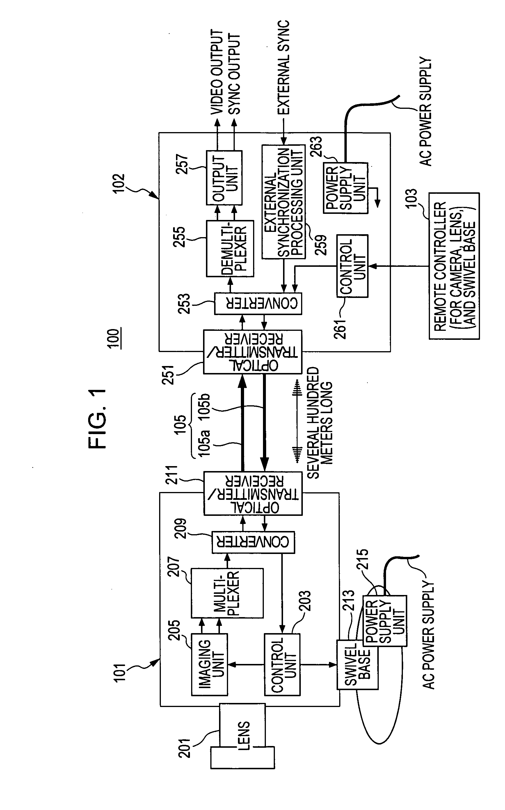
[0042]FIG. 1 is a schematic block diagram of an imaging apparatus 100 according to an embodiment of the present invention.

[0043] As shown in FIG. 1, the imaging apparatus 100 includes a camera device 101, a signal processor 102, a remote controller 103, and an optical fiber cable 105. The imaging apparatus 100 may include a plurality of camera devices 101, signal processors 102, and remote controllers 103.

[0044] The camera device 101 photographs an object to generate a video signal, and performs processing, such as multiplexing, on the generated video signal. The resulting video signal is then transmitted to the signal processor ...


PUM


Abstract

An imaging apparatus includes a camera device, a signal processor that receives a video signal from the camera, and a connection cable connecting the camera device and the signal processor. The camera device includes a first phase controller that compares the phase of a synchronization signal transmitted from the signal processor with the phase of an internal signal generated by the camera device, and that synchronizes the phase of the internal signal with the phase of the synchronization signal, a video synchronization signal generator that generates a video synchronization signal for the video signal based on the internal signal, and a signal transmitter that transmits the video signal. The signal processor includes a second phase controller that compares the phase of the video synchronization signal with the phase of the synchronization signal, and that synchronizes the phase of the video synchronization signal with the phase of the synchronization signal.

Description

BACKGROUND OF THE INVENTION [0001] 1. Field of the Invention [0002] The present invention relates to an imaging apparatus including an optical fiber cable. More specifically, the present invention relates to an imaging apparatus, to a phase control method therefor, and to a synchronization method therefor. [0003] 2. Description of the Related Art [0004] Various imaging systems (imaging apparatuses) have been commercially available for the purpose of security. One known imaging system is a monitoring system in which video from one or a plurality of cameras installed in a place, such as an office building or a house, is observed by an operator on a monitor. [0005] This type of imaging apparatus or monitoring system has a network that carries data, such as a video signal generated by video captured with the camera or cameras, over which the data is transmitted from the camera or cameras to the monitor (see, for example, Japanese Unexamined Patent Application Publication No. 7-212748). ...

Claims


Application Information

Patent Timeline
Patent Type & Authority Applications(United States)
IPC IPC(8): H04N5/04H04N5/073H04N5/225H04N5/232H04N7/18H04N7/22
CPCH04N5/23203H04N5/0733H04N23/66H04N7/22H04N5/04H04N7/18
Inventor NAKAJIMA, TAKATSUGU
Owner SONY CORP
Why Eureka
Try Eureka