Image forming apparatus, erasing method, and hard disk management method

a technology of image forming apparatus and erasing method, which is applied in the direction of erasing method, digital output to print unit, instruments, etc., can solve the problems of affecting the accuracy of erasing process,

Active Publication Date: 2005-08-11
RICOH KK
View PDF22 Cites 13 Cited by
  • Summary
  • Abstract
  • Description
  • Claims
  • Application Information

AI Technical Summary

Benefits of technology

[0024] A further specific object of the present invention is to provide an image forming apparatus and a

Problems solved by technology

The erasing process takes a relatively large amount of time since the HDD recently becomes larger in addition to a large size of the image data.
Moreover, if the multi-functional apparatus mounts the HDD, a security problem concerning information recorded in the HDD is raised.
After that, it becomes quite difficult to predict original magnetic data.
However, a method for practically realizing this method has not been introduced.
Further

Method used


Image

  • Image forming apparatus, erasing method, and hard disk management method
  • Image forming apparatus, erasing method, and hard disk management method
  • Image forming apparatus, erasing method, and hard disk management method

Examples


first embodiment

[0089]FIG. 5 is a diagram showing a configuration of a multi-functional apparatus according to the first embodiment of the present invention. The multi-functional apparatus 1 includes a software group 2, a boot part 3, and hardware resources 4.

[0090] The boot part 3 is executed first when the multi-functional apparatus 1 is turned on, and activates an application layer 5 and a platform layer 6. For example, the boot part 3 reads out programs of the application layer 5 and the platform layer 6 from a hard disk device (hereinafter, called HDD) or a like, and transfers each of the programs, which are read out from the HDD, into a memory area and activates the programs. The hardware resources 4 include a scanner 25, a plotter 26, and other hardware resources 24 such as an ADF (Auto Document Feeder).

[0091] The software group 2 includes the application layer 5 and the platform layer 6 which are activated on an operating system (hereinafter, called OS) such as UNIX™. The application laye...

second embodiment

[0170] In the following, an erasing method for erasing information recorded in a hard disk will be described. Hereinafter, erasing information recorded in the hard disk (for example, HDD 38 in FIG. 6) may be expressed as erasing or overwriting information recorded in the hard disk.

[0171]FIG. 24 is a diagram for explaining the erasing method for erasing information recorded on a hard disk, according to a second embodiment of the present invention. In FIG. 24, a disk 101 of the hard disk and a sector / cluster 102are shown. Random numbers are over written at a first time and a second time and zero is overwritten at a third time, with respect to the sector / cluster 102. The sector / cluster 102 denotes a sector or a cluster.

[0172] As described above, erase information used to erase information recorded in the hard disk and an erasing method for erasing the information in a case of overwriting three times will be described by illustrating three examples.

[0173] A first example will be desc...

third embodiment

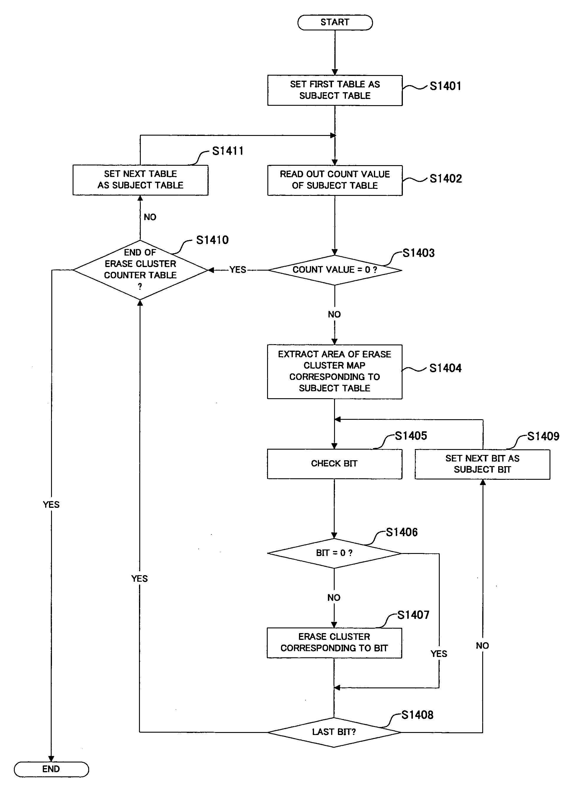
[0200] In the following, a method for managing and overwriting the HDD 38 will be described. First, for example, as shown in FIG. 29, an image to record to the HDD 38 is input by the scanner 25 mounted in the multi-functional apparatus 1 or a PC 402 connected through a network. The image being input is recorded in a RAM 403 and then recorded in the HDD 38.

[0201] In the HDD 38, areas are defined based on a type of information to record. FIG. 30 shows the areas. As shown in FIG. 30, the areas are defined as a temporary area 421, a system area 422, and other areas 423.

[0202] The temporary area 421 is used to record a temporary image. For example, the temporary image is an image read at a copy. In general, the read image is recorded in the HDD 38 once and deleted after the read image is printed on a paper sheet.

[0203] The system area 422 is used by a system of the multi-functional apparatus 1. The other areas 423 include an image accumulation area, a user address book, and a capture....


PUM


Abstract

An image forming apparatus includes a plurality of erase information each showing whether or not to erase data for each of a plurality of divided areas into which the hard disk is divided, group erase information showing groups grouping the erase information, and erase count information determined based on the group erase information. Based on the erase count information whether or not there is a divided area to erase, the divided area is erased.

Description

BACKGROUND OF THE INVENTION [0001] 1. Field of the Invention [0002] The present invention generally relates to image forming apparatuses, erasing methods, and hard disk management methods, and more particularly to an image forming apparatus mounting a hardware disk, an erasing method for erasing information stored in the hard disk thereof, and a hard disk management method. [0003] 2. Description of the Related Art [0004] Recently, an image forming apparatus (hereinafter, called multi-functional apparatus) accommodating functions of a facsimile, a printer, a copier, and a scanner into a single chassis has been widely known. In the multi-functional apparatus, a displaying part, a printing part, an imaging part, and a like are arranged within the single chassis, and also four applications corresponding to the facsimile, the printer, the copier, and scanner are included. By switching the four applications, the multi-functional apparatus operates as the facsimile, the printer, the copier...

Claims


Application Information

Patent Timeline
IPC IPC(8): G06F3/06G11B5/024H04N1/32
CPCG06F3/0613G06F3/0623G11B5/024G06F3/0676G06F3/0652
Inventor HATTORI, YASUHIROSATOH, KENSHINDOH, HIDENORIYAMAZAKI, TAKAHIRO
Owner RICOH KK
Why Eureka
Try Eureka