LED light bulb and its application in a desk lamp

Inactive Publication Date: 2005-08-11
YONG GAO +1
View PDF7 Cites 317 Cited by
  • Summary
  • Abstract
  • Description
  • Claims
  • Application Information

AI Technical Summary

Benefits of technology

[0012] As such, the innovated eye-friendly LED light bulb enjoys an even and a large area i

Problems solved by technology

Traditional illumination lights such as the incandescent light bulbs and the fluorescent lights, normally working under a voltage of 110V or 220V, though bright enough, suffer drawbacks like poor power efficiency, short product life, and a sometimes dazzling brightness.
The LEDs, on the contrary, work under

Method used


Image

  • LED light bulb and its application in a desk lamp
  • LED light bulb and its application in a desk lamp
  • LED light bulb and its application in a desk lamp

Examples


Example

[0021] In the drawings like characters of reference indicate corresponding parts in the different figures.

DETAILED DESCRIPTION

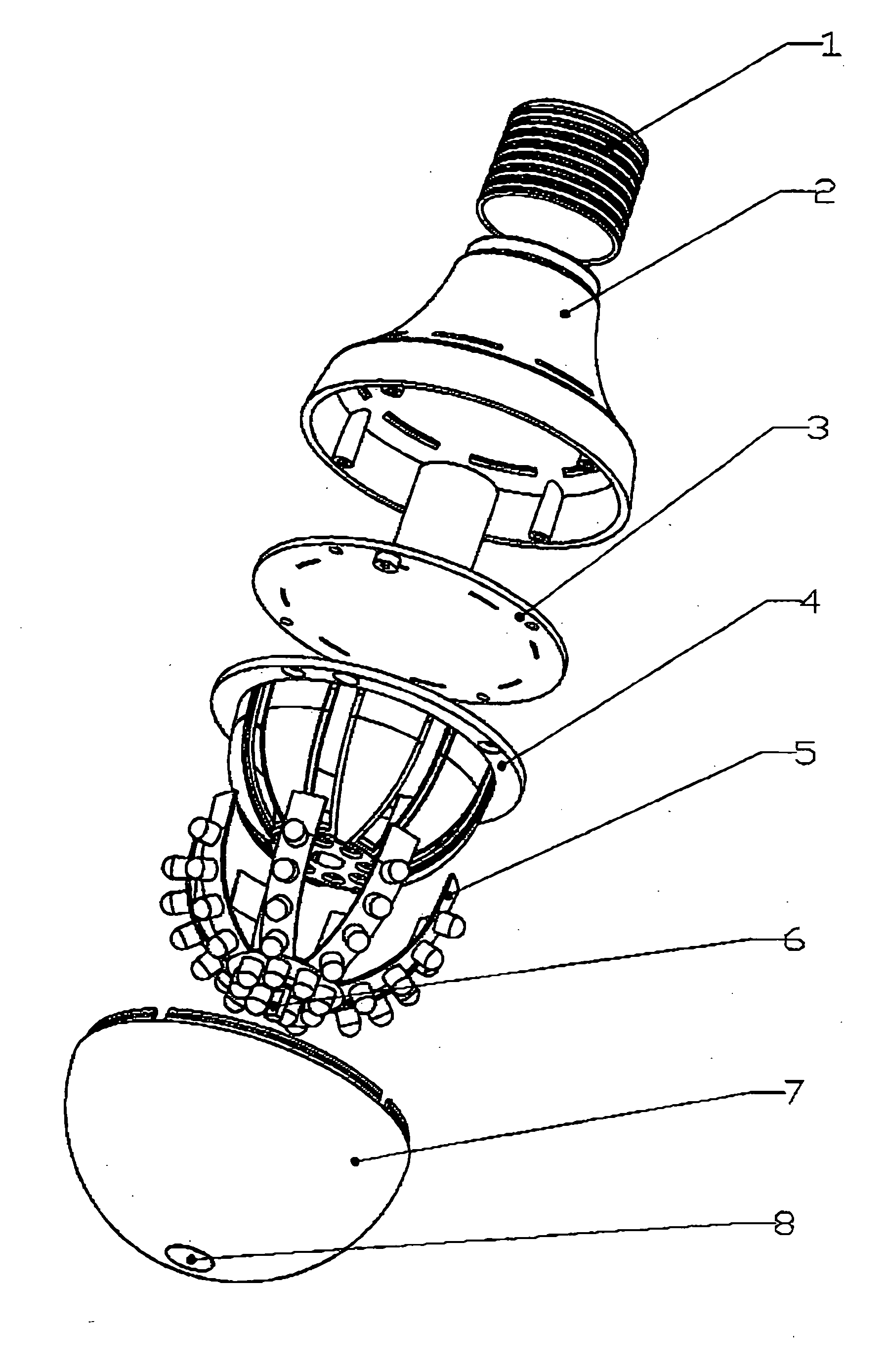
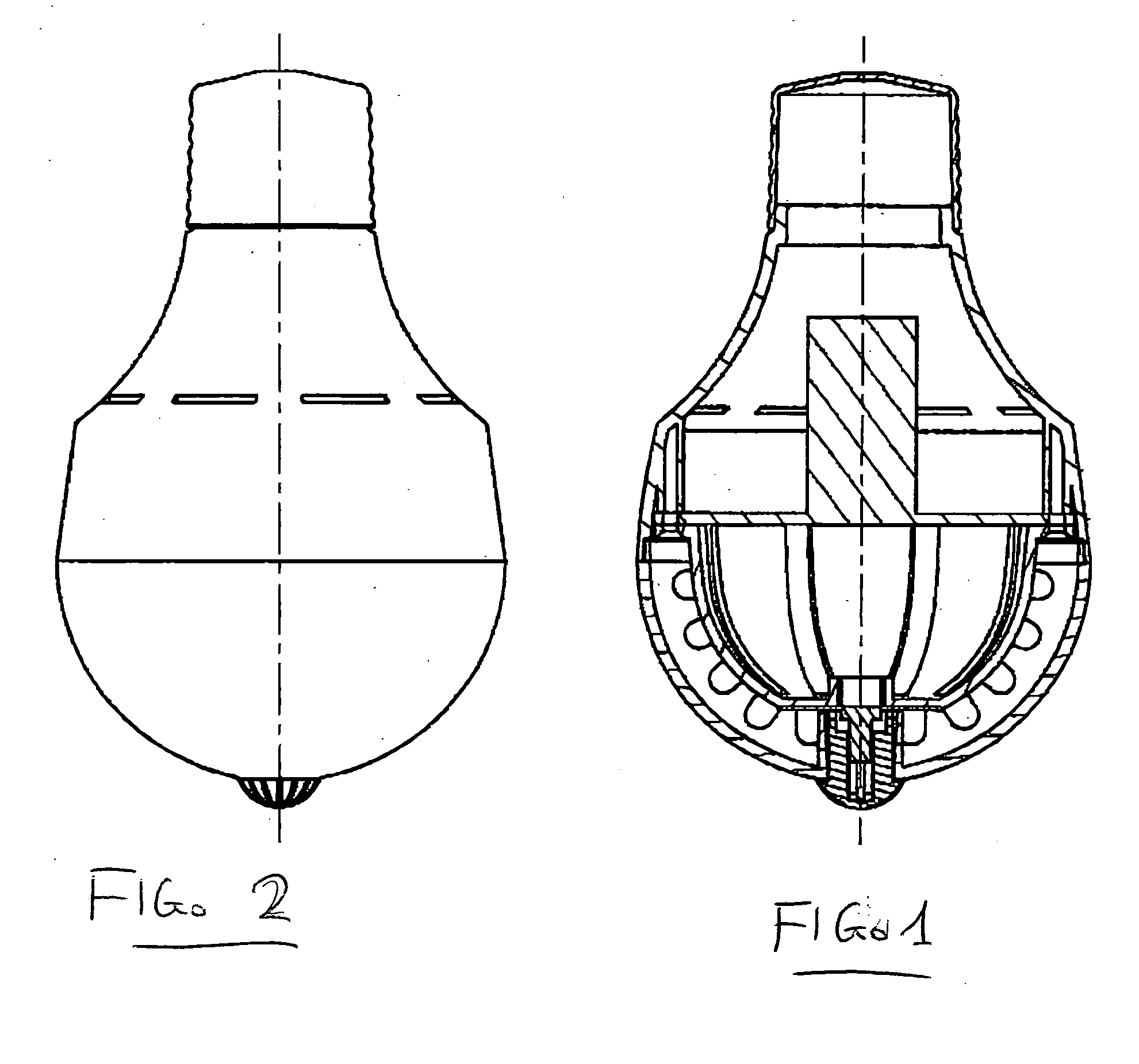
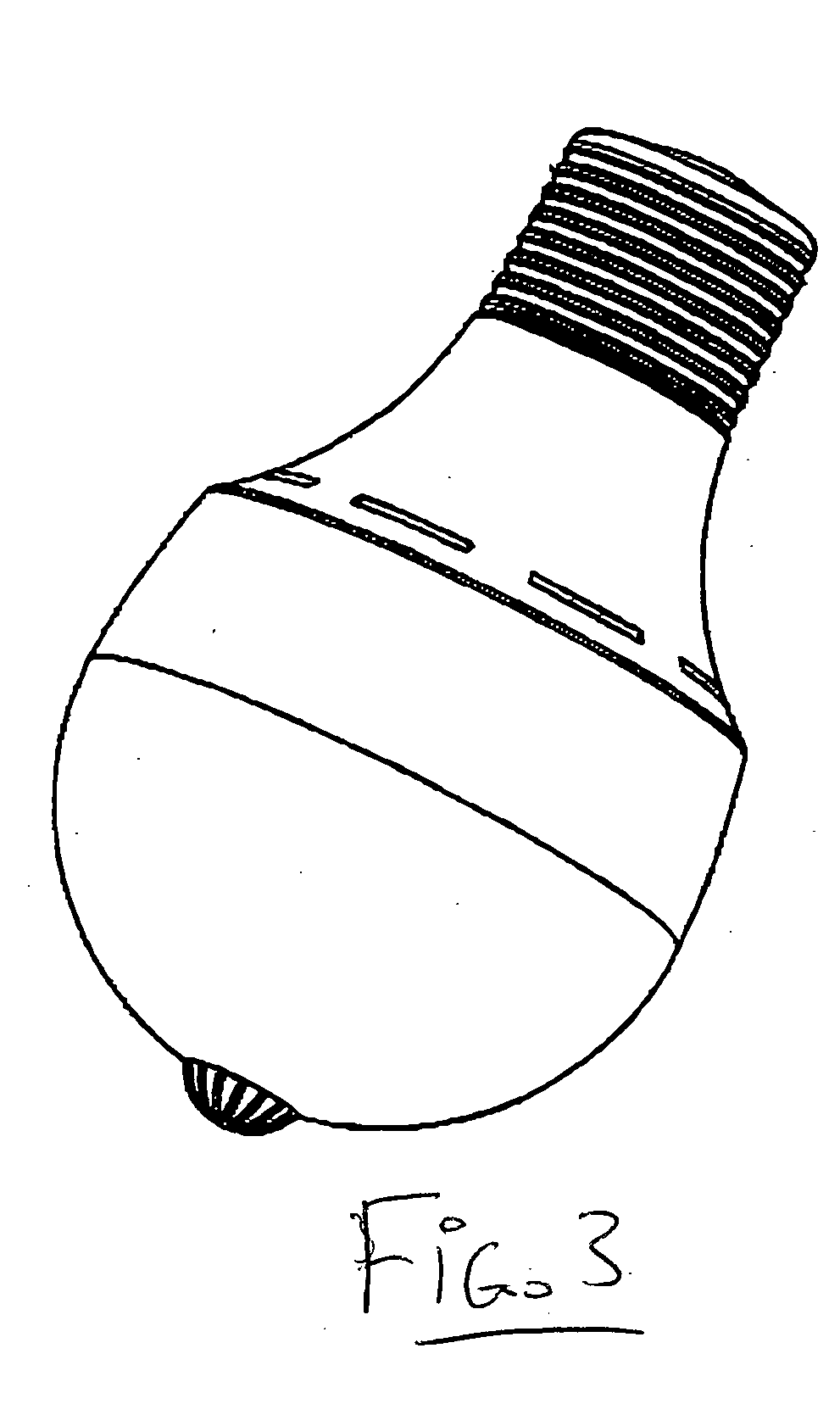
[0022] The structure of sample product 1 is showed in FIG. 1 to FIG. 4, from which can be seen that bulb shell consists of two parts, namely, the Lower Shell (7), which is made of a transparent material and Upper Shell (2), which is made either of the same material as the Lower Shell, or of an opaque material. The Upper Shell meets the screw base at one end and the two parts of shell together contain a round PCB (3), a frame (4), a star shaped PCB (5) which has a plurality of arms spreading from a center, and LEDs (6). The AD / DC converter is fixed on the round PCB (3), which converts the alternating current coming through the screw base to low voltage direct current which the LEDs work on. The frame (4) has eight curving arms arranged in a star shaped pattern, along the top curves of which the LEDs are distributed. The internal schematic view of the star sh...


PUM


Abstract

An LED light bulb includes a screw base, a shell formed by two halves of hemispherical shells connecting tightly in the middle and a number of LEDs distributed spherical symmetrically on a curved flexible PCB inside an inner front of the shell, where the LEDs are series or parallel connected and arranged, when working, to emit light evenly in all directions. The LED light bulb can be used in a desk lamp.

Description

[0001] This invention involves an innovated LED light bulb, specifically, a bulb with LED units distributed symmetrically on a curved PCB inside its shell, and a desk lamp using the bulb. BACKGROUND OF THE INVENTION [0002] Traditional illumination lights such as the incandescent light bulbs and the fluorescent lights, normally working under a voltage of 110V or 220V, though bright enough, suffer drawbacks like poor power efficiency, short product life, and a sometimes dazzling brightness. The LEDs, on the contrary, work under a low DC voltage with very low power waste as well as a long product life. As a result, LED light bulbs have been developed and put into practical use. However, the customary practice in the industry of arranging LED units on a flat plane in matrix or other forms brings a new problem. Because an LED emits light with high convergence, a group of LEDs arranged on a flat plain facing the same direction causes the narrow space centered along this direction to be il...

Claims


Application Information

Patent Timeline
IPC IPC(8): F21K99/00
CPCF21K9/135F21Y2101/02F21V3/02F21Y2111/004F21Y2111/001F21K9/232F21Y2115/10F21Y2107/00F21Y2107/20
Inventor YONG, GAOWANG, YA
Owner YONG GAO
Why Eureka
Try Eureka