Lamp assembly having variable focus and directionality

a technology of variable focus and assembly, applied in the field of light assembly, can solve the problems of large overall assembly, cumbersome and expensive manufacture, deficiency of suman et al. light assembly, etc., and achieve the effect of convenient operation

Active Publication Date: 2005-08-11
REBO LIGHTING & ELECTRONICS LLC
View PDF18 Cites 50 Cited by
  • Summary
  • Abstract
  • Description
  • Claims
  • Application Information

AI Technical Summary

Benefits of technology

[0012] Accordingly, these various aspects of the subject invention provide a lighting assembly for interior vehicular illumination which is both directionally and focus adjustable, and which is convenient to operate.

Problems solved by technology

Although Logel uses a unitary structure to accomplish all of these functions, the overall assembly is nevertheless large, cumbersome and expensive to manufacture.
Variable focus lighting assemblies have been proposed with limited functionality.
The Suman et al. light assembly is deficient however, in that the light beam pattern is directionally adjustable only when in the spot lighting condition; it is immobile in the flood lighting condition.
These multiple inputs can present an inconvenience, as well as a distraction to the driver.

Method used


Image

  • Lamp assembly having variable focus and directionality
  • Lamp assembly having variable focus and directionality
  • Lamp assembly having variable focus and directionality

Examples


Embodiment Construction

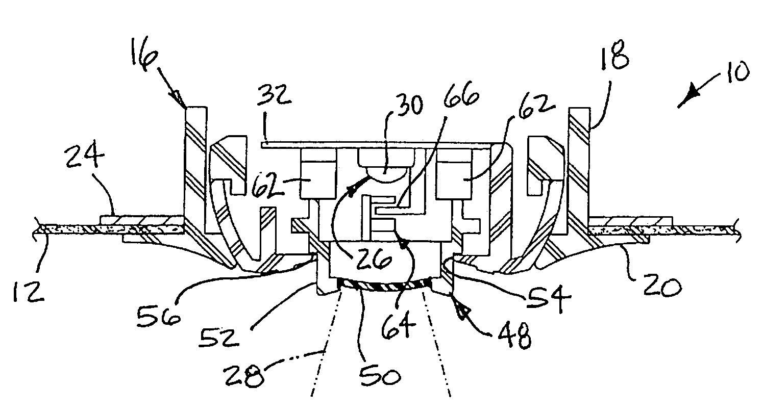
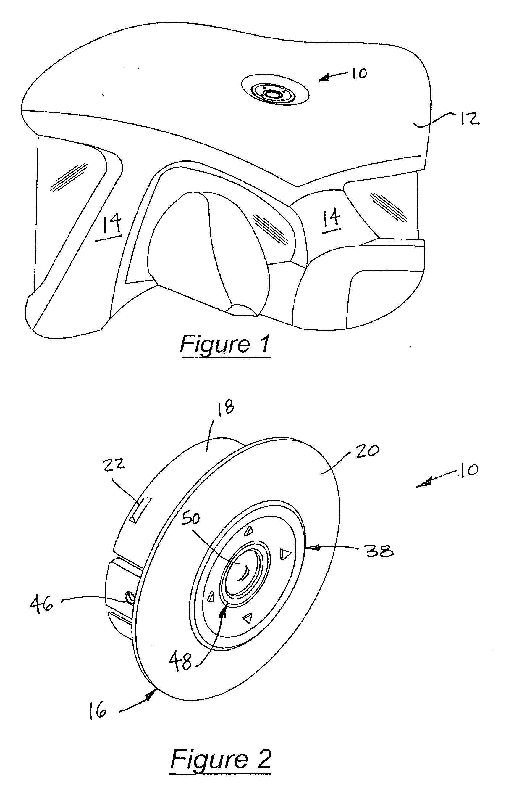
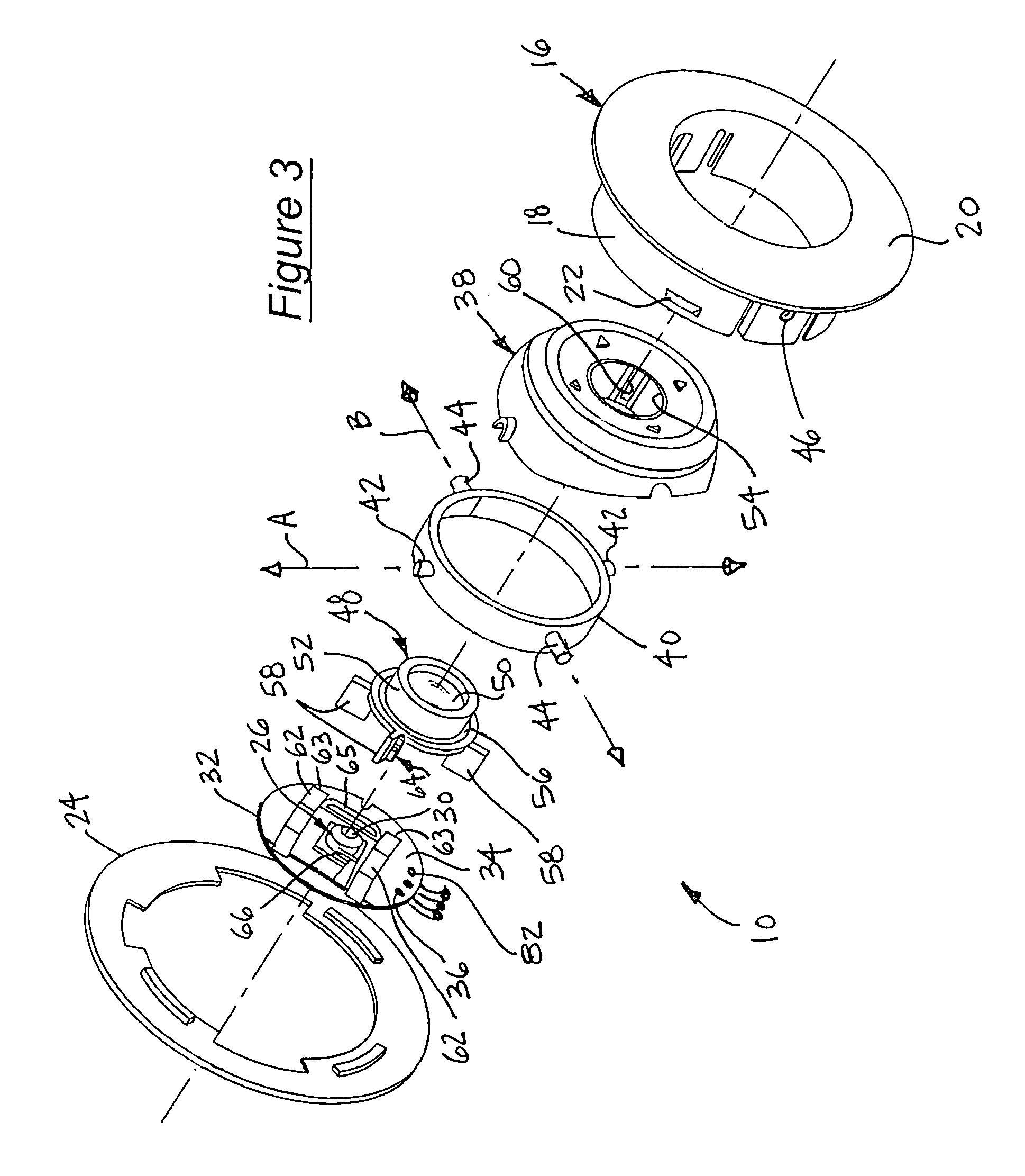
[0023] Referring to the figures, wherein like numerals indicate like or corresponding parts throughout the several views, a lighting assembly according to the subject invention is generally shown at 10 in FIG. 1 positioned within a headliner 12 under the roof of a motor vehicle. For reference, B and C pillars 14 are shown extending from the headliner 12. Although mounting the lighting assembly 10 within the headliner 12 is a preferred application of the invention, the lighting assembly 10 can be conveniently located in other portions of a motor vehicle, including within the trim features of the pillars 14, in a door panel, in a console or armrest, in the dashboard, in the trunk area, in the engine compartment, or in any other convenient location. The lighting assembly 10 is adjustable between flood and spot lighting conditions so that regardless of its location within the motor vehicle, it is useful for both general and task lighting. Furthermore, the lighting assembly 10 is fully d...


PUM


Abstract

A lighting assembly (10) is adjustable between flood and spot lighting conditions for selectively illuminating an interior passenger compartment in a motor vehicle. The assembly (10) includes a housing (16) which clamps to a supporting member, such as a headliner (12), via a sleeve (18) interacting with a rotary cam lock (22). An LED light source (26) is orbitally supported within the housing (16) for projecting light in a directionally adjustable manner. A lens (50) is disposed in the light path (28) and is moveable between an extended spot position for task lighting and a retracted flood position for general illumination within the interior compartment. A switch (74) is responsive to movement of the lens (50) into its spot position for automatically energizing the LED (30). The switch (74) opens, thus de-energizing the LED (30) when the lens (50) is returned to its flood condition. A lighting control circuit (78, 78′) is responsive to an override signal, such as from a door switch (80, 80′), for independently activating the light source (26) when the lens (50) is in its flood position. The light source (26) is supported for orbital movement within the housing (16) by a gimbal mechanism which includes an inner gimbal (38) carried in a cross (40). Pintals (42, 44) establish intersecting perpendicular axis (A,B) to accomplish the orbital movement. A latch mechanism (64) cooperates with leaf springs (62) by controlling movement of the lens (50) between its flood and spot conditions by a repeated push impulse applied by the finger of an operator. The switch (74) is incorporated into the leaf springs (62).

Description

BACKGROUND OF THE INVENTION [0001] 1. Field of the Invention [0002] This invention relates generally to lighting assemblies for illuminating the interior passenger compartment of a motor vehicle, and more specifically toward a lighting assembly which is adjustable between flood and spot lighting conditions and also directionally adjustable. [0003] 2. Related Art [0004] Lighting assemblies are well known for use in motor vehicle interior cabins, trunks, engine compartments, and other environments where light is needed. Such lighting assemblies provide direct lighting, indirect lighting, and backlighting, among other applications, and have become smaller, more efficient, more durable and longer lasting. Typically, indirect, or general illumination lighting is accomplished by dome lamp assemblies or other lighting device which disperses light over a large area. This is in contrast to direct or task lighting applications, such as map or reading lights, where light from the light source ...

Claims


Application Information

Patent Timeline
Patent Type & Authority Applications(United States)
IPC IPC(8): B60Q3/00B60Q3/02
CPCB60Q3/001B60Q3/0296B60Q3/0293B60Q3/0279B60Q3/82B60Q3/74B60Q3/85B60Q3/80
Inventor BYNUM, STEPHEN A.
Owner REBO LIGHTING & ELECTRONICS LLC
Why Eureka
Try Eureka