
Method for performing measurements for handoff of a mobile unit operating with a switched beam antenna in a wireless communication system, and corresponding system

a wireless communication system and mobile unit technology, applied in the field of wireless communication, can solve the problems of increased hard handoff, increased call drop, and low amplitude of neighboring cell reception signal power to trigger the transmission of a measurement report, so as to improve the soft handoff, increase the number of dropped calls, and increase the hard handoff rate

Inactive Publication Date: 2005-08-11
INTERDIGITAL TECH CORP
View PDF28 Cites 45 Cited by
  • Summary
  • Abstract
  • Description
  • Claims
  • Application Information

AI Technical Summary

Benefits of technology

[0021] When using only the selected beam for measurements, the received signal power from the neighboring cells may be too low in amplitude to trigger the transmission of a measurement report to the network. Thus, a soft handoff may not be triggered which could lead to a higher rate of hard handoffs and increase the number of dropped calls.
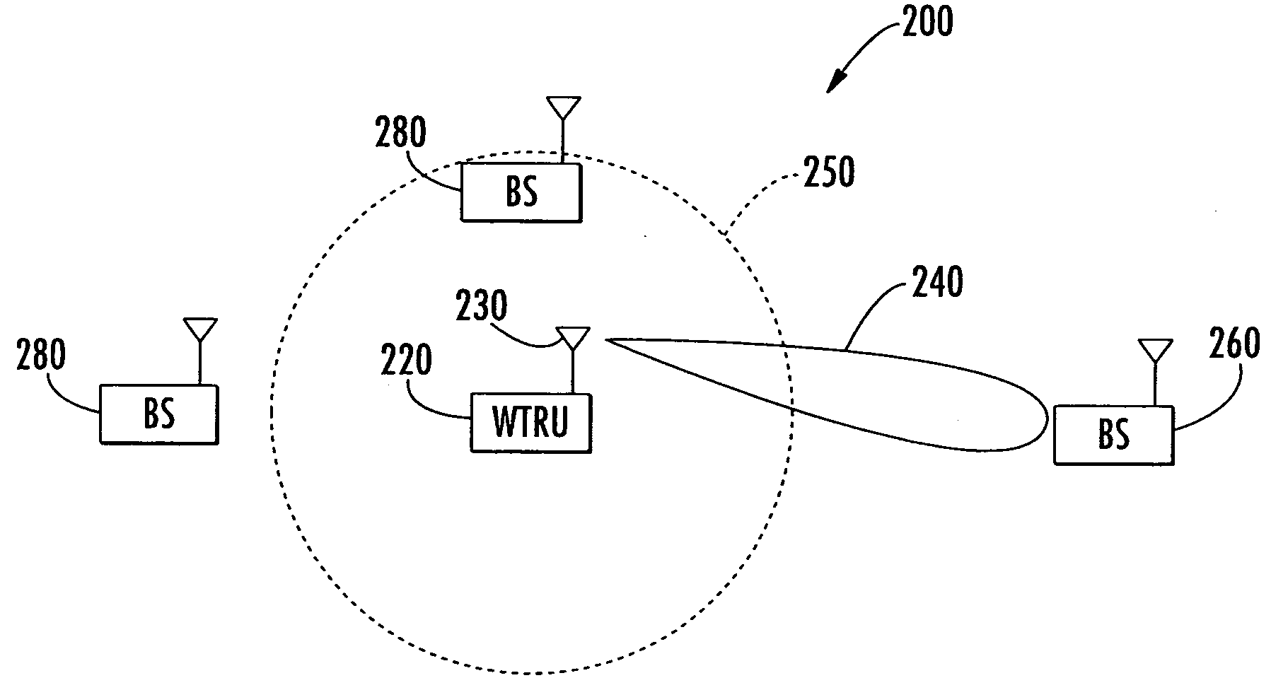
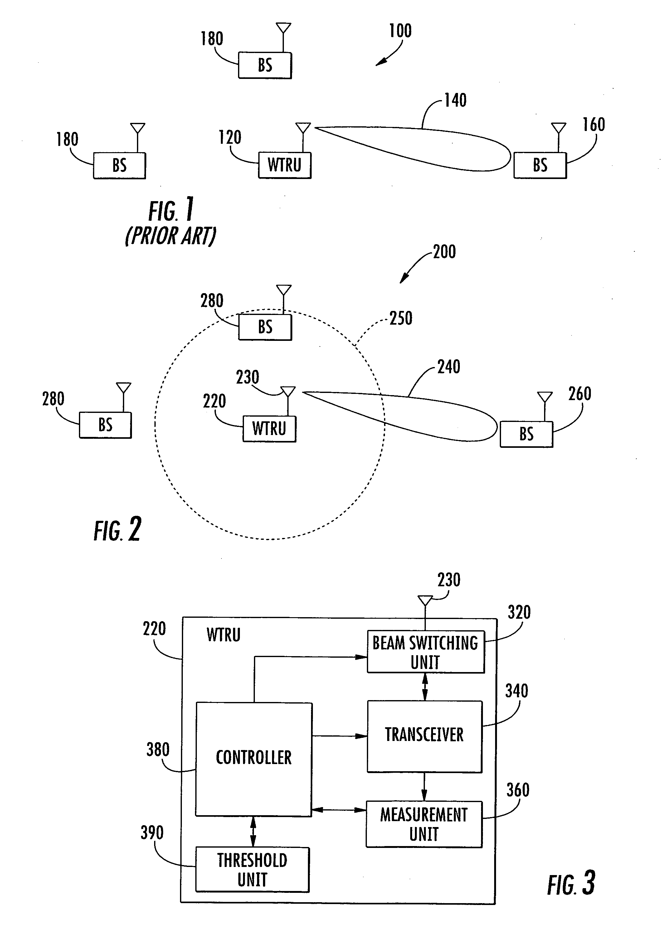
[0022] With this invention, the WTRU advantageously evaluates and reports to the network measurement of signals received from the cells in the omni-directional beam and / or the directional beams with the strongest measurement for adding cells to the active set of cells. By adding cells to the active set of cells based on measuring signals in the first through the sixth embodiments, soft handoff is improved so that connectivity of the mobile WTRU operating with a switched beam antenna in a multi-cell wireless communication system is better maintained.

Problems solved by technology

The received signal power from the neighboring cells may be too low in amplitude to trigger the transmission of a measurement report to the network.
Thus, a soft handoff may not be triggered which could lead to a higher rate of hard handoffs and increase the number of dropped calls.

Method used


Image

  • Method for performing measurements for handoff of a mobile unit operating with a switched beam antenna in a wireless communication system, and corresponding system
  • Method for performing measurements for handoff of a mobile unit operating with a switched beam antenna in a wireless communication system, and corresponding system
  • Method for performing measurements for handoff of a mobile unit operating with a switched beam antenna in a wireless communication system, and corresponding system

Examples


first embodiment

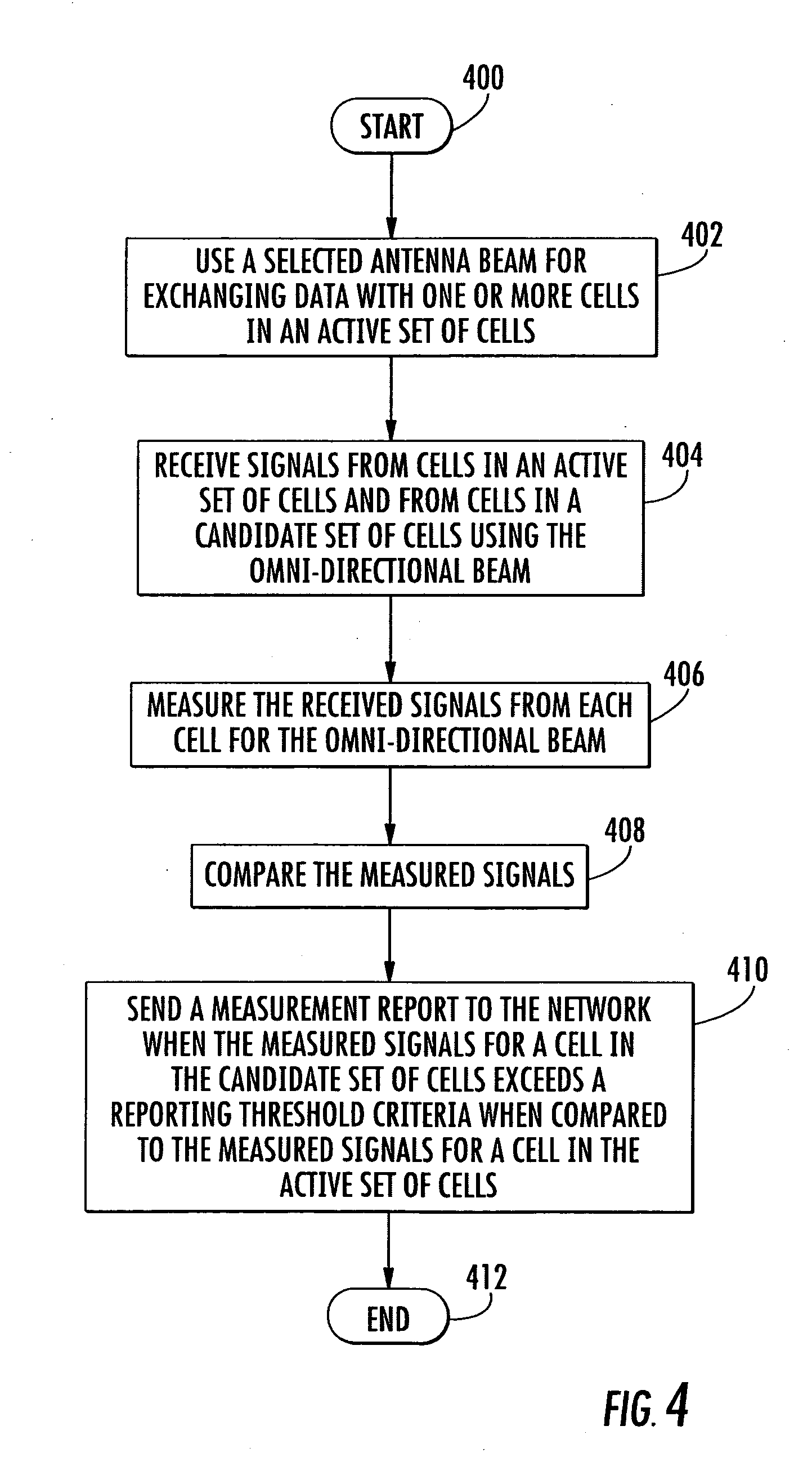
[0035] the method for performing antenna beam measurements and reporting of the measurements to the network while operating with the switched beam antenna 230 is illustrated in the flow diagram in FIG. 4. From the start (Block 400), the WTRU 220 uses a selected antenna beam for exchanging data with one or more cells in an active set of cells at Block 402, receives signals from cells in the active set of cells and from cells in the candidate set of cells using the omni-directional beam 250 at Block 404. The received signals for the omni-directional beam 250 are measured at Block 406.

[0036] The WTRU 220 compares the measured signals in the omni-directional beam 250 at Block 408. A measurement report is sent to the network at Block 410 when the measured signals for a cell in the candidate set of cells exceeds a reporting threshold criteria when compared to the measured signals for a cell in the active set of cells. The method ends at Block 412. This process repeats from Block 400 for t...

second embodiment

[0037] The second embodiment is illustrated in the flow diagram of FIG. 5. From the start (Block 500), the WTRU 220 uses a selected antenna beam for exchanging data with a cell in the active set of cells at Block 502.

[0038] Signals are received from cells in the active set of cells and from cells in a candidate set of cells using the selected directional beam and the omni-directional beam at Block 504. The received signals for both the selected directional beam and the omni-directional beam are measured at Block 506. The measured signal having the highest value from each cell in the active set of cells and in the candidate set of cells are selected at Block 508. That is, for each cell, the highest measured signal (the omni-directional beam measurement or the selected directional beam measurement) is selected.

[0039] The selected measured signals are compared at Block 510. A measurement report is sent to the network at Block 512 when the selected measured signals for a cell in the ca...

third embodiment

[0040] The third embodiment is illustrated in the flow diagram of FIG. 6. From the start (Block 600), a selected antenna beam is used for exchanging data with one ore more cells in an active set of cells at Block 602, signals are received from cells in the active set of cells and from cells in the candidate set of cells using the plurality of directional beams and the omni-directional beam at Block 604.

[0041] The received signals are measured for each directional beam and the omni-directional beam at Block 606. The measured signal having the highest value are selected from each cell in the active set of cells and in the candidate set of cells at Block 608. That is, for each cell, the highest measured signal (the omni-directional beam measurement or the highest directional beam measurement) is selected. The selected measured signals are compared at Block 6010. A measurement report is sent to the network at Block 612 when the selected measured signals for a cell in the candidate set o...


PUM


Abstract

Measurements for handoff are made by a wireless transmit / receive unit (WTRU) operating with a switched beam antenna in a wireless communication system. The switched beam antenna is a smart antenna generating a plurality of directional beams and an omni-directional beam. The WTRU measures signals from a plurality of cells with the omni-directional beam and / or one or more of the directional beams. The WTRU evaluates and reports to the network measurement of the omni-directional beam or the strongest beam for adding cells to an active set of cells. For removing cells from an active set of cells, the WTRU evaluates and reports to the network measurements of the antenna beam selected for communication with the active set cells.

Description

RELATED APPLICATION [0001] This application claims the benefit of U.S. Provisional Application Ser. No. 60 / 541,967 filed Feb. 5, 2004, the entire contents of which are incorporated herein by reference.FIELD OF THE INVENTION [0002] The present invention relates to the field of wireless communications, and more particularly, to the handoff of a mobile wireless transmit / receive unit (WTRU) operating with a switched beam antenna in a multi-cell wireless communication system. BACKGROUND OF THE INVENTION [0003] In a wireless multi-cell communication system, a mobile WTRU typically moves from one cell to another. As the WTRU crosses the boundary of a cell, a handoff is initiated. A handoff is a procedure in which communication in an active cell is transferred to another cell without interruption. During soft handoff, the same data is received and transmitted between the WTRU and the two cells. [0004] The terminology “active set” refers to the set of cells communicating (i.e., transmitting ...

Claims


Application Information

Patent Timeline
IPC IPC(8): H04B15/00H04J13/00H04W16/28H04W36/18
CPCH04W36/18H04W16/28H04W36/185H04B1/707H04B7/0408
Inventor STERN-BERKOWITZ, JANETIACONO, ANA LUCIAZANGI, KAMBIZ CASEY
Owner INTERDIGITAL TECH CORP
Learn More