
Portable wireless terminal

a wireless terminal and portability technology, applied in the structure of radiating elements, substation equipment, collapsable antenna means, etc., can solve the problems of increasing hand influence, corresponding losses, and degrading antenna radiation characteristics, so as to reduce the influence of hand influen

Inactive Publication Date: 2005-08-11
SONY ERICSSON MOBILE COMM JAPAN INC
View PDF4 Cites 12 Cited by
  • Summary
  • Abstract
  • Description
  • Claims
  • Application Information

AI Technical Summary

Benefits of technology

[0009] From the above, it is an object of the present invention to provide a portable wireless terminal having a hinge section provided type antenna suitable for a clamshell type which can maintain spacing from the head of a human body and alleviate the influence of the hand of a user.
[0010] It is a further object of the present invention to provide a portable communication terminal apparatus which has a speaker facing a placing surface and achieving not only prevention of degradation of sound quality but also extended radiation of sound into the surrounding space to transmit sound into the surroundings relatively uniformly.
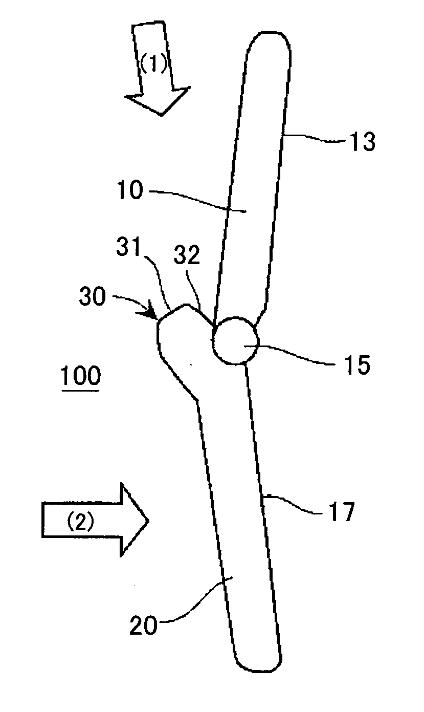
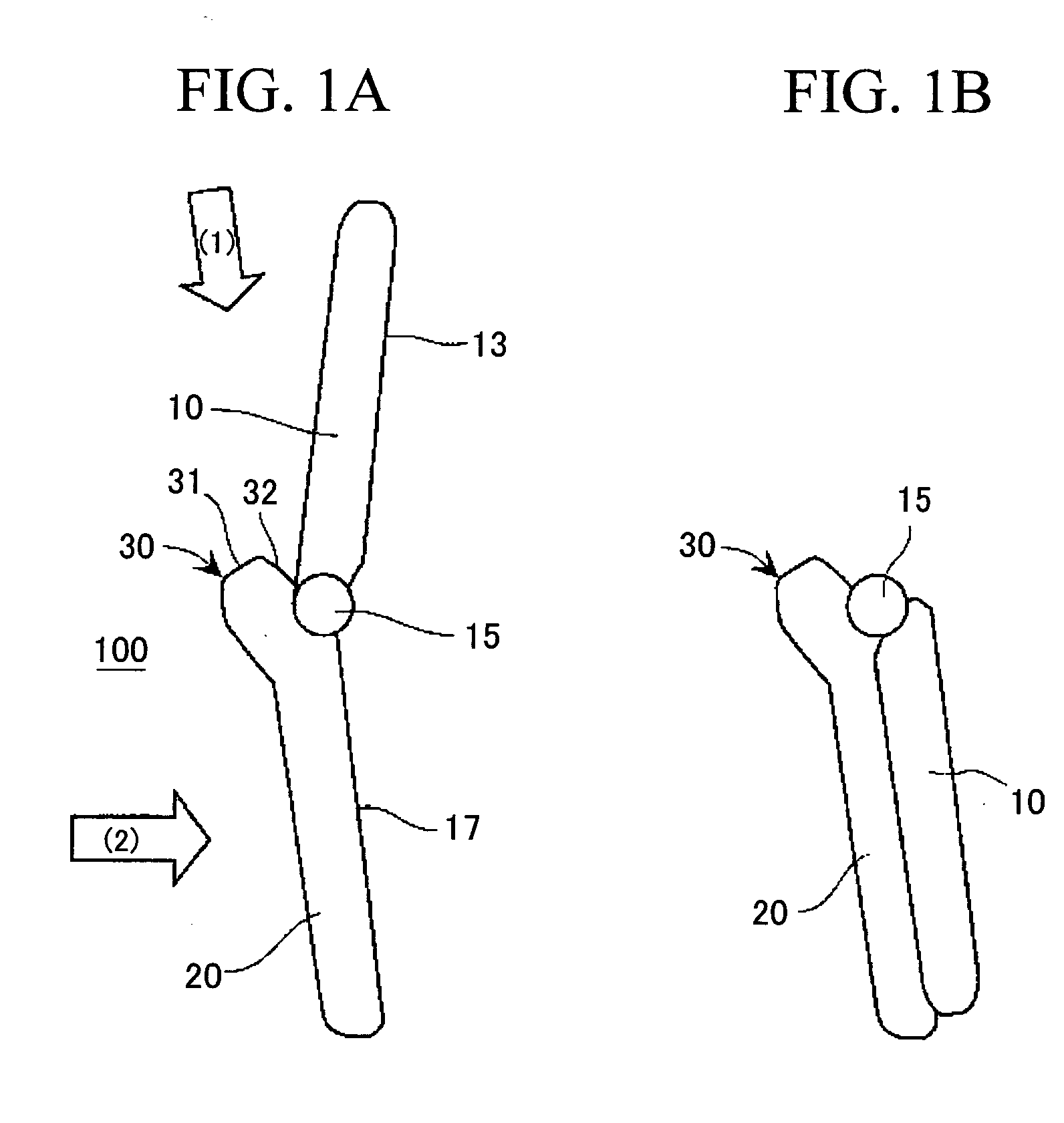
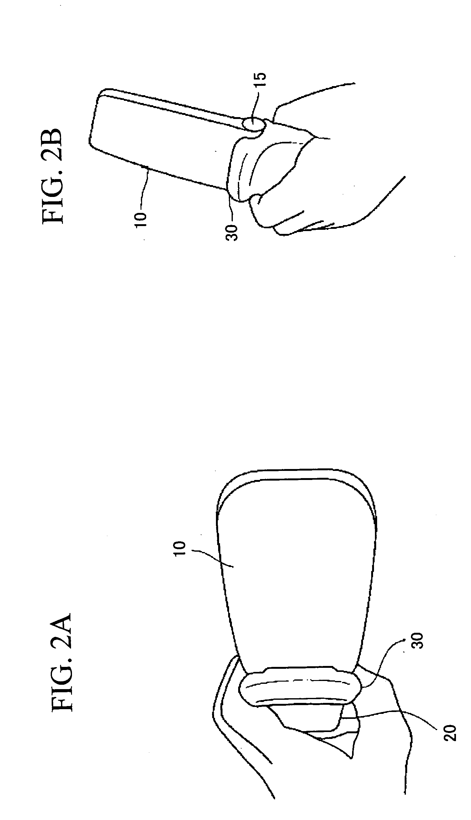
[0012] Since the portable wireless terminal has the built-in antenna housed in the projection section near the hinge section of the clamshell type portable wireless terminal, space for providing the antenna can be ensured. In addition, a relatively long distance between the antenna and the head is maintained during a telephone call. Furthermore, since a user often makes a call by holding a portion near the hinge section, the hand or finger of the user is closer to the antenna section in this structure. However, the antenna open end portion of the antenna element which is likely to be effected by a human body particularly is disposed at a position which is unlikely to be covered by the hand or finger of the user, thereby significantly reducing degradation of antenna characteristics when the terminal is used.
[0013] As one aspect, the antenna element is formed of a first element portion having a base end side connected to a feed point and a second element portion having a main surface forming a predetermined angle with a main surface of the first element portion. The second element portion is connected to a side portion on an end side of the first element portion and forms part of the open end side. Since the main surfaces of both element portions form the predetermined angle, the single antenna element has surfaces at different angles. This structure avoids a situation in which both main surfaces are simultaneously covered by the hand or finger of the user depending on how the user holds the housing.
[0017] According to another standpoint, the portable wireless terminal according to the present invention is characterized by a clamshell type portable wireless terminal having an upper housing and a lower housing connected to each other through a hinge, comprising an antenna element having a first element portion in a flat plate shape having a base end side connected to a feed point and a second element portion in a flat plate shape connected to a side portion on the end side of the first element portion and having a main surface forming a predetermined angle with a main surface of the first element portion, the antenna element being disposed within the housing near a hinge section along a housing width direction. This structure serves to avoid a situation in which both main surfaces are simultaneously covered by the hand or finger of the user depending on how the user holds the housing since both element portions form the predetermined angle.
[0018] According to a further standpoint, the portable wireless terminal according to the present invention is characterized by a clamshell type portable wireless terminal having an upper housing and a lower housing connected to each other through a hinge, comprising, a built-in antenna disposed near a hinge portion along a housing width direction, the build-in antenna having an antenna element in a flat plate shape having a base end side connected to a feed point, in a state in which a hand or finger of a user is closest to an open end side of the antenna element from outside the housing in an open state, a main surface of the antenna element forming the right angle or an angle near the right angle with respect to a surface of the hand or finger at least over a predetermined length on the open end side. This structure serves to reduce the influence of the hand or finger of the user on the antenna at least on the open end side of the antenna element.

Problems solved by technology

Thus, an antenna section mounted on the terminal is closer to a human body during a telephone call, so that concerns are rising that antenna radiation characteristics are degraded.
However, “provided in the upper portion of the upper housing” type generally must have a coaxial cable routed from a transmission / reception circuit (a wireless circuit) section provided within the lower housing to an antenna power supply section through the hinge section to cause the disadvantage that losses are produced corresponding thereto.
In addition, since the upper housing unit tends to have a reduced thickness for design in recent years, there are disadvantages that the space for providing the antenna is not sufficient, the distance between the antenna and the head of a user is short to degrade antenna characteristics during a telephone call, and the like.
Furthermore, depending on preferences of a user, the hinge section provided type antenna has the disadvantage in terms of the antenna characteristics that, when the portion of the housing including the antenna projects, the user conveniently uses the terminal by putting his finger on the projected portion since his hand is stable.
In this case, there are problems that radiation of sound emitted from a sound emitting port is prevented and sound quality is degraded.
This problem applies to a so-called stick type of mobile phone.
However, the size of open space formed between the housing and the placing surface for transmitting sound from the speaker is tilted in some directions, so that the problem occurs that sound is not necessarily radiated in the surroundings uniformly.

Method used


Image

  • Portable wireless terminal
  • Portable wireless terminal
  • Portable wireless terminal

Examples


first embodiment

[0057] Since the space below a speaker section 18 is released (opened) in three directions of the front, left, and right in this embodiment, sound can be transmitted in the surroundings more uniformly as compared with the

[0058]FIGS. 14A to 14C shows the structure of a mobile phone according to a third embodiment of the present invention. While this is similar to the mobile phone of the second embodiment except for the following point. Specifically, projection sections 64 in two separate parts are also provided at an end portion on the opposite side to an end portion on the side of a hinge of a lower housing 20. This forms an opening section 65 symmetric on both sides on a placing section 40 and forms an opening 62 which is substantially symmetric in the front-to-back direction. Since the space below a speaker section 18 is released in fourth directions of the front, back, left, and right in this embodiment, sound can be transmitted in the surroundings more uniformly as compared with...

seventh embodiment

[0062]FIG. 18A to FIG. 18C shows the structure of a mobile phone according to the present invention. This is a mobile phone which has a projection section 116 accommodating a whip antenna 114 and has a projection section 111 with the equal size to this projection on the side portion on the opposite side. The projection section 111 has no antenna accommodated therein. The antenna 114 may be a fixed antenna which cannot be extended. This structure allow the mobile phone to be stably placed on a placing surface and forms opening sections 112 symmetric on both sides and an opening section 62 in front in which the space facing a speaker section 18 connects to the surroundings. In other words, the space facing the speaker section 18 is released in three directions of the opening section 62 and the two opening sections 112. Thus, sound can be transmitted in the surroundings more uniformly than the conventional one.

eighth embodiment

[0063]FIG. 19A to FIG. 19C shows the structure of a mobile phone according to the present invention. This is not a clamshell type but a straight type mobile phone. Projection sections 113 in separate two parts are provided on the rear side of a housing, that is, on the opposite side to the side where a liquid crystal display section 13 is positioned. The projection sections 113 form an opening section 62 opened to the rear side and opening sections 105 opened symmetrically on both sides on a placing surface 40. In other words, the space facing a speaker section 18 is released in three directions of the opening section 62 and the two opening sections 105. Thus, sound can be transmitted in the surroundings more uniformly than the conventional one. In this embodiment, the projection section 113 may be formed to extend in the width direction of the housing.

[0064] While preferred embodiments of the present invention have been described, various modifications and variations are possible o...


PUM


Abstract

A portable wireless terminal has a hinge section provided type antenna suitable for a clamshell type which can maintain spacing from a head of a human body and alleviate influence of a hand of a user. The clamshell type portable wireless terminal having an upper housing (10) and a lower housing (20) connected to each other through a hinge has a projection section (30) projecting outward near a hinge section of the lower housing (20). In addition, a built-in antenna is housed in the projection section (30). The built-in antenna has an antenna element (50) in a linear or plate shape. At least a part of the antenna element on an open end side is disposed at a position which is hardly to be covered by the hand or finger of the user when the user uses the terminal.

Description

TECHNICAL FIELD [0001] The present invention relates to a portable wireless terminal, and particularly, to a built-in antenna of a portable wireless terminal for use in communication between mobile units for example a mobile phone, and to the structure and arrangement of a sound emitting port of a speaker which generates ringtone. BACKGROUND ART [0002] Portable wireless terminals for communication between mobile units such as a mobile phone (in the present specification, a terminal apparatus is simply referred to as a terminal) tend to have a reduced size and thickness. Thus, an antenna section mounted on the terminal is closer to a human body during a telephone call, so that concerns are rising that antenna radiation characteristics are degraded. [0003] In recent years, instead of terminals which employ an accommodation / extension type of whip antenna provided externally to the terminal, terminals which employ a so-called built-in antenna provided inside the terminal have come on th...

Claims


Application Information

Patent Timeline
Patent Type & Authority Applications(United States)
IPC IPC(8): H01Q1/08H01Q1/24H01Q1/36H04M1/02
CPCH01Q1/243H01Q1/084H04B1/38
Inventor SAWAMURA, MASATOSHI
Owner SONY ERICSSON MOBILE COMM JAPAN INC
Learn More