Conical, threaded subtalar implant

Active Publication Date: 2005-08-11
OSTEOMED
View PDF24 Cites 63 Cited by
  • Summary
  • Abstract
  • Description
  • Claims
  • Application Information

AI Technical Summary

Benefits of technology

[0005] The present invention provides a conical, threaded medical implant adapted for implantation within a person's body to limit motion in a joint having excessive mobility. In some embodiments, a medical implant includes a body having a conical portion and adapted for implantation into a person's body. A plurality of threads formed around an exterior surface of the conical portion of the body are ada

Problems solved by technology

In addition, the insert may include threads that are sharp enough to help hold the insert in place within the person's sinu

Method used


Image

  • Conical, threaded subtalar implant
  • Conical, threaded subtalar implant
  • Conical, threaded subtalar implant

Examples


Embodiment Construction

[0014] According to the present invention, a conical, threaded medical implant is adapted for implantation within a person's body to limit motion in a joint having excessive mobility. In certain embodiments, the medical implant is a subtalar implant adapted for implantation into the person's body and sized to fit within a sinus tarsi of a subtalar joint in the person's body for at least partially preventing displacement of the talus. However, it should be understood that various implants discussed herein may be otherwise used without departing from the scope of the invention.

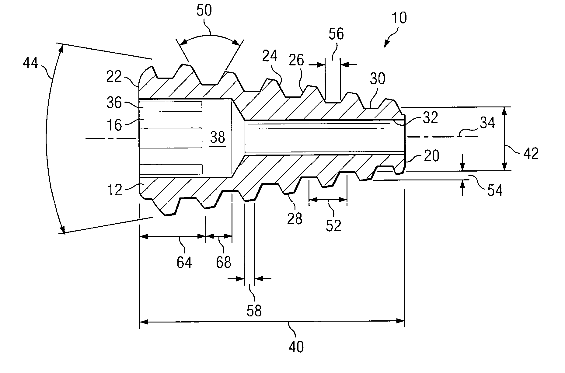
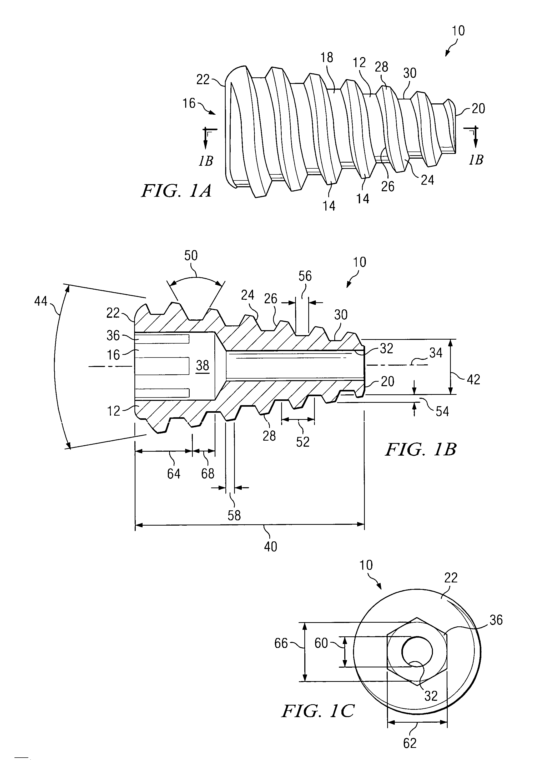
[0015]FIGS. 1A-1C illustrate a subtalar implant 10 in accordance with one embodiment of the present invention. In particular, FIG. 1A illustrates an external side view of implant 10, FIG. 1B illustrates a cross-sectional view of implant 10 taken along line A-A of FIG. 1A, and FIG. 1C illustrates an external end view of implant 10. In general, subtalar implant 10 may be inserted into the sinus tarsi of a person ...


PUM


Abstract

A medical implant includes a body having a conical portion and adapted for implantation into a person's body. A plurality of threads formed around an exterior surface of the conical portion of the body are adapted to help secure the implant in place within the person's body.

Description

TECHNICAL FIELD [0001] This invention relates generally to biomedical implants and in particular to conical, threaded subtalar implants and methods for manufacturing the same. BACKGROUND [0002] Pes planus, or pes valgo planus, is a deformity producing a severe flat foot. The deformity occurs largely at one particular joint, the talocalcaneal articulation, which is the joint between the talus and calcaneus bones in the foot. There are typically three separate components of a valgus deformity at this joint: first, the calcaneus has a valgus position; second, the head of the talus angulates downward; and third, the forefoot is totally abducted in relation to the hindfoot. In addition, the Achilles tendon may be pulled laterally due to the outward rotation, or eversion, of the calcaneus. [0003] Pes valgo planus often results from the failure of the arch to form in one or both feet of a child aged two to four, which is the typical age for the natural formation of the arch in the foot. Th...

Claims


Application Information

Patent Timeline
IPC IPC(8): A61B17/56A61B17/58A61B17/86A61F2/00A61F2/30A61F2/42
CPCA61B17/562Y10S606/916A61F2002/3021A61F2002/30214A61F2002/30215A61F2002/30563A61F2002/30565A61F2002/30594A61F2002/30616A61F2002/30777A61F2002/3079A61F2002/30851A61F2002/30858A61F2002/30874A61F2002/4207A61F2002/4223A61F2230/0067A61F2310/00023A61F2/4202A61F2002/30873
Inventor ZANG, KERRYAHMAD, SHAHER A.THORNHILL, LISA R.
Owner OSTEOMED
Why Eureka
Try Eureka