
Low-overhead built-in timestamp column for relational database systems

a database system and built-in timestamp technology, applied in the field of database systems, can solve the problems of not being updated very frequently, requiring additional space for the timestamp, and requiring additional cpu costs

Inactive Publication Date: 2005-08-11
IBM CORP
View PDF14 Cites 27 Cited by
  • Summary
  • Abstract
  • Description
  • Claims
  • Application Information

AI Technical Summary

Benefits of technology

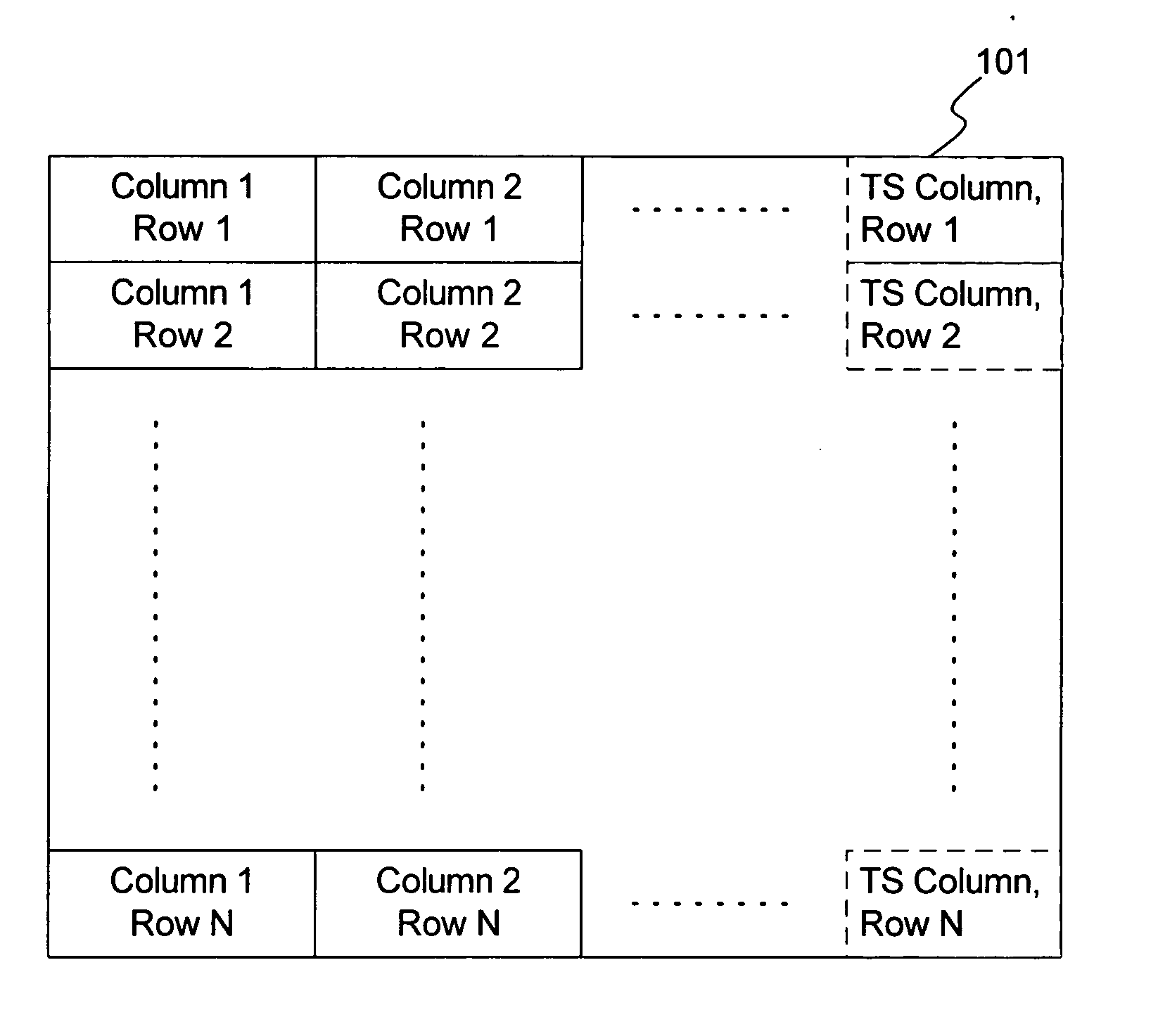
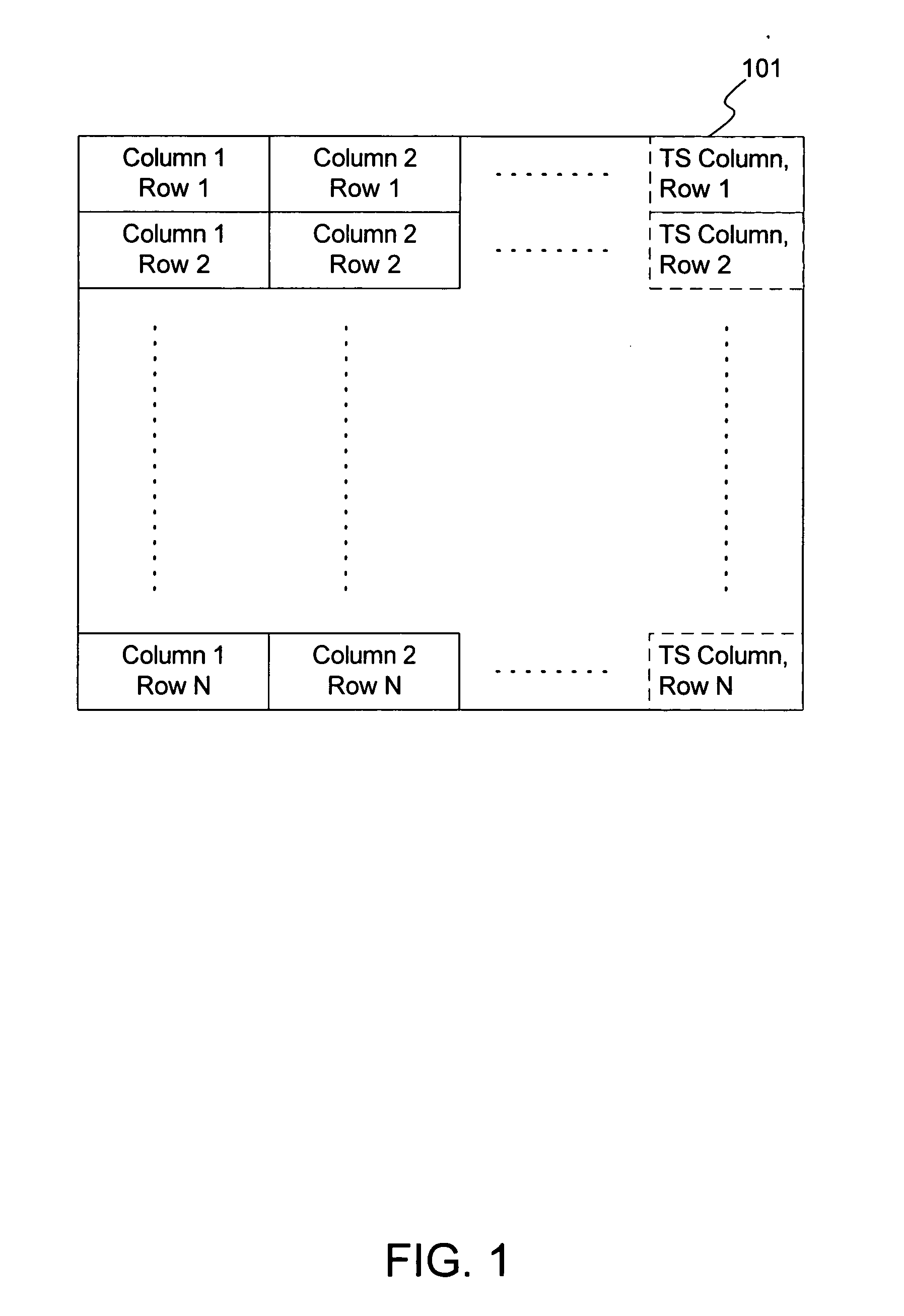
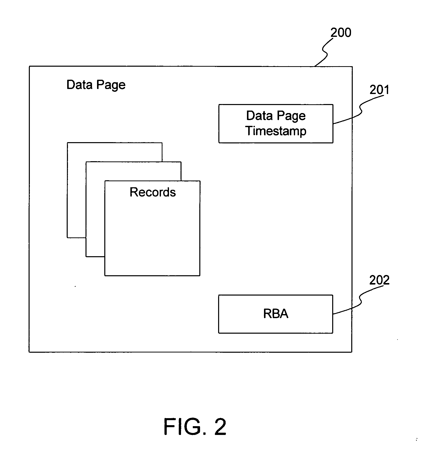
[0007] An improved automatically updated timestamp for database systems is disclosed. The automatically updated timestamp can be provided in a hidden timestamp column for a table, where the value of the timestamp column can be retrieved with a query that calls the column by name. Optionally, the timestamp column can be provided for each table in the database system to ensure its availability to applications. For cases where a timestamp for each row in a table is not desired, an automatically updated timestamp can be provided for a data page. This timestamp can be retrieved from an update timestamp recorded on disk and in the buffer pool or from a log relative byte address. Although this is a page-level timestamp, its use may be desirable for infrequently updated tables or where space on the disk and buffer pool is at a premium.

Problems solved by technology

If the timestamp column is not the same, the disconnected update fails, and the application has to re-drive the update process using the modified data row.
First, it requires additional CPU cost to maintain the timestamp column in each data row.
Second, some tables may not be updated very frequently, so it may not be worthwhile to require the additional space for the timestamp in every row.
Third, if the timestamp column has to be explicitly added to the table by the user, shrink-wrapped client applications cannot assume that the timestamp column will necessarily be present, since the user may have chosen not to add the timestamp column.
So, client applications will be reluctant to exploit this feature of the database.
Fourth, having an explicit column for the timestamp is also inconvenient for cases where some applications need the extra column while others do not.
For example, adding the extra timestamp column for one application might cause problems for other existing applications that didn't expect this extra column to be part of the table schema.

Method used


Image

  • Low-overhead built-in timestamp column for relational database systems
  • Low-overhead built-in timestamp column for relational database systems
  • Low-overhead built-in timestamp column for relational database systems

Examples


Embodiment Construction

[0010] The present invention provides an improved automatically updated timestamp for database systems. The following description is presented to enable one of ordinary skill in the art to make and use the invention and is provided in the context of a patent application and its requirements. Various modifications to the preferred embodiment will be readily apparent to those skilled in the art and the generic principles herein may be applied to other embodiments. Thus, the present invention is not intended to be limited to the embodiment shown but is to be accorded the widest scope consistent with the principles and features described herein.

[0011] To more particularly describe the features of the present invention, please refer to FIGS. 1 and 2 in conjunction with the discussion below.

[0012]FIG. 1 illustrates a first preferred embodiment of an automatically updated timestamp for database systems in accordance with the present invention. In the first preferred embodiment, a built-i...


PUM


Abstract

An improved automatically updated timestamp for database systems is disclosed. The automatically updated timestamp can be provided in a hidden timestamp column for a table, where the value of the timestamp column can be retrieved with a query that calls the column by name. Optionally, the timestamp column can be provided for each table in the database system to ensure its availability to applications. For cases where a timestamp for each row in a table is not desired, an automatically updated timestamp can be provided for a data page. This timestamp can be retrieved from an update timestamp recorded on disk and in the buffer pool or from a log relative byte address. Although this is a page-level timestamp, its use may be desirable for infrequently updated tables or where space on the disk and buffer pool is at a premium.

Description

FIELD OF THE INVENTION [0001] The present invention relates to database systems, and more particularly to providing timestamps in database systems. BACKGROUND OF THE INVENTION [0002] The need for data replication in a database system, particularly a distributed database system, is well known in the art. To ensure data consistency, modifications to different copies of a table must be replicated across all copies. To facilitate the updating of the table copies, timestamps are typically used to indicate which rows have been modified since the last update. Conventionally, a timestamp column that is automatically updated each time a row is modified is provided for this purpose. If the timestamp value in the timestamp column is later than the time of the last update, then that row has been modified since the last update. [0003] Applications commonly use this timestamp column for controlling optimistic locking schemes as follows: the application retrieves one or more rows from the table, i...

Claims


Application Information

Patent Timeline
Patent Type & Authority Applications(United States)
IPC IPC(8): G06F17/00G06F17/30
CPCG06F17/30595G06F16/284Y10S707/99943Y10S707/99933
Inventor CHEN, YAO-CHING STEPHENCOTNER, CURT L.
Owner IBM CORP
Learn More