Storage system

a storage system and storage system technology, applied in the field of storage systems, can solve the problems of inability to guarantee the scalability of performance, the difficulty of etc., and achieve the effect of improving the access performance in the u.s., reducing the cost of the storage system in a small scale configuration, and improving the performance of the storage system in the futur

Inactive Publication Date: 2005-08-11
HITACHI LTD
View PDF36 Cites 23 Cited by
  • Summary
  • Abstract
  • Description
  • Claims
  • Application Information

AI Technical Summary

Benefits of technology

[0014] If cost is not considered, it is possible to improve the access performance in U.S. Pat. No. 6,385,681 by increasing the scale of the cache memory unit 14 and the control information memory unit. However, in order to access the cache memory unit 14 or the control information memory unit 15 from all the channel IF units 11 and the disk IF units 16, it is necessary to manage the cach...

Problems solved by technology

This results in an access load bottleneck, which makes it difficult to improve performance of t...

Method used


Image

  • Storage system
  • Storage system
  • Storage system

Examples


first embodiment

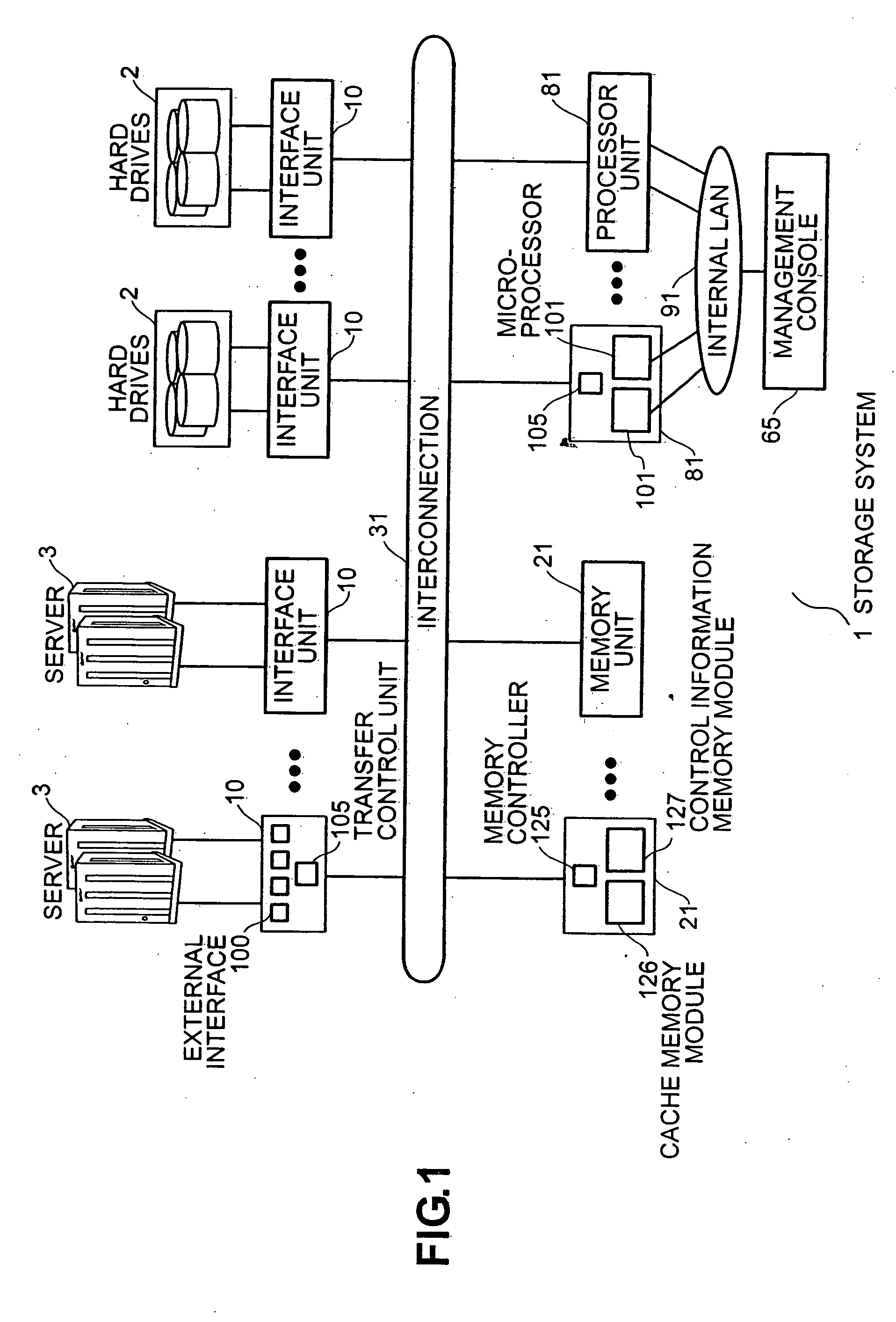
[0047]FIG. 1 is a diagram depicting a configuration example of the storage system according to the The storage system 1 is comprised of interface units 10 for transmitting / receiving data to / from a server 3 or hard drives 2, processor units 81, memory units 21 and hard drives 2. The interface unit 10, processor unit 81 and the memory unit 21 are connected via the interconnection 31.

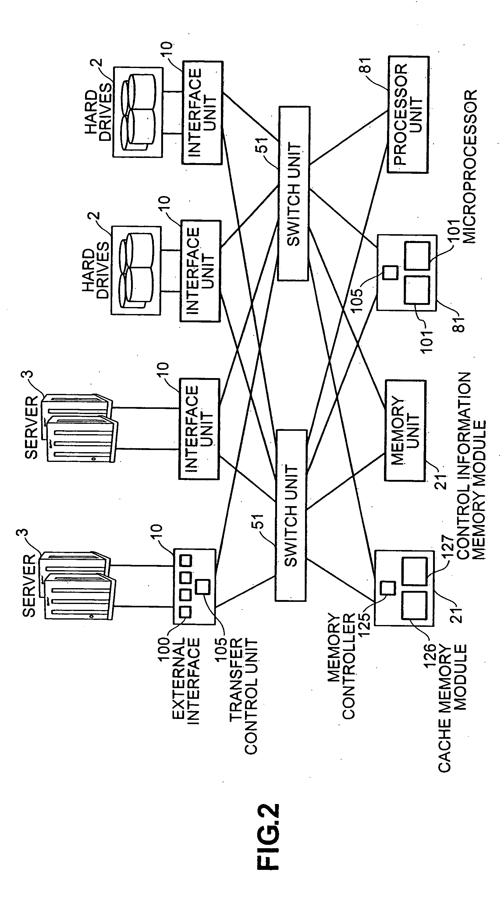
[0048]FIG. 2 is an example of a concrete configuration of the interconnection 31.

[0049] The interconnection 31 has two switch units 51. The interface units 10, processor unit 81 and memory unit 21 are connected to each one of the two switch units 51 via one communication path respectively. In this case, the communication path is a transmission link comprised of one or more signal lines for transmitting data and control information. This makes it possible to secure two communication routes between the interface unit 10, processor unit 81 and memory unit 21 respectively, and improve reliability. The above ...

second embodiment

[0123]FIG. 5 is a diagram depicting a configuration example of the

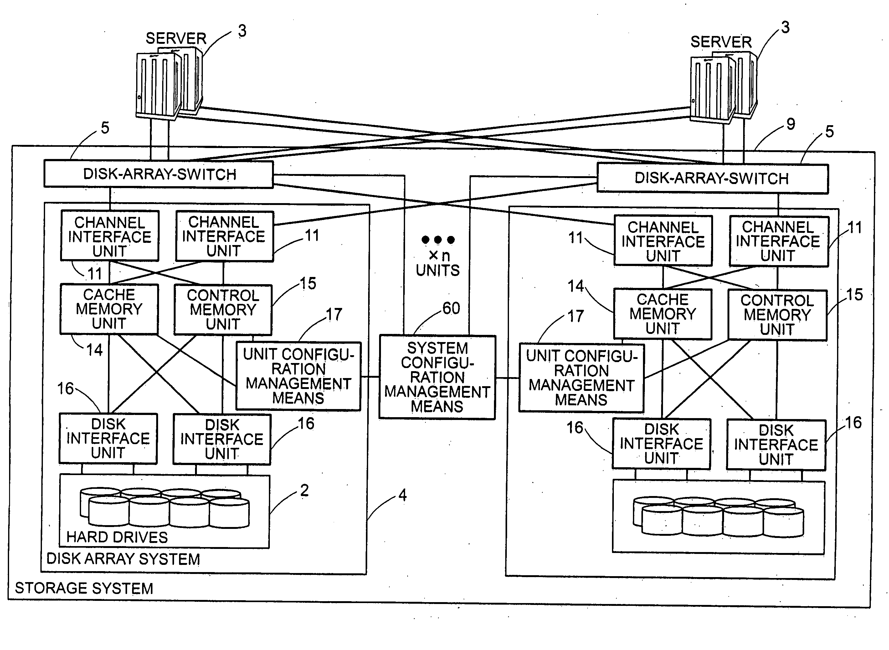
[0124] The storage system 1 has a configuration where a plurality of clusters 70-1-70-n are interconnected with the interconnection 31. One cluster 70 has a predetermined number of interface units 10 to which the server 3 and hard drives 2 are connected, memory units 21, and processor units 81, and a part of the interconnection. The number of each unit that one cluster 70 has is arbitrary. The interface units 10, memory units 21 and processor units 81 of each cluster 70 are connected to the interconnection 31. Therefore each unit of each cluster 70 can exchange packets with each unit of another cluster 70 via the interconnection 31. Each cluster 70 may have hard drives 2. So in one storage system 1, clusters 70 with hard drives 2 and clusters 70 without hard drives 2 may coexist. Or all the clusters 70 may have hard drives.

[0125]FIG. 6 is a diagram depicting a concrete configuration example of the interconnection 31....


PUM


Abstract

A storage system is comprised of an interface unit 10 which has an interface with a server 3 or hard drives 2, a memory unit 21 which has a cache memory module 126 for storing data to be read from/written to the server 3 or the hard drives 2 and a control information memory module 127 for storing control information of the system, a processor unit 81 which has a microprocessor for controlling the read/write of data between the server 3 and the hard drives 2, and an interconnection 31, wherein the interface unit 10, memory unit 21 and processor unit 81 are interconnected with the interconnection 31.

Description

CROSS-REFERENCES TO RELATED APPLICATIONS [0001] This application relates to and claims priority from Japanese Patent Application No. 2004-032810, filed on Feb. 10, 2004, the entire disclosure of which is incorporated herein by reference. BACKGROUND OF THE INVENTION [0002] 1. Field of the Invention [0003] The present invention relates to a storage system which can expand the configuration scalably from small scale to large scale. [0004] 2. Description of the Related Art [0005] Storage systems for storing data to be processed by information processing systems are now playing a central role in information processing systems. There are many types of storage systems, from small scale configurations to large scale configurations. [0006] For example, the storage system with the configuration shown in FIG. 20 is disclosed in U.S. Pat. No. 6,385,681. This storage system is comprised of a plurality of channel interface (hereafter “IF”) units 11 for executing data transfer with a computer (her...

Claims


Application Information

Patent Timeline
IPC IPC(8): G06F3/06G06F13/40
CPCG06F13/4022G06F13/14
Inventor FUJIMOTO, KAZUHISAINOUE, YASUOHOSOYA, MUTSUMISHIMADA, KENTAROWATANABE, NAOKI
Owner HITACHI LTD
Why Eureka
Try Eureka