Eureka AIR delivers breakthrough ideas for toughest innovation challenges, trusted by R&D personnel around the world.

Electromagnetic valve operating device with adjustable neutral position

Inactive Publication Date: 2005-08-18
BAYERISCHE MOTOREN WERKE AG
View PDF5 Cites 0 Cited by
  • Summary
  • Abstract
  • Description
  • Claims
  • Application Information

AI Technical Summary

Benefits of technology

[0011] In the case of the exhaust valve, it is useful, during the start of the engine or in the low-load operation, to bring the control element or the armature plate into a neutral position which corresponds to the center position between the two solenoids. In this neutral position, the armature plate is equally far away from both solenoids if they are not energized. On the other hand, in operation under a load, it is advantageous with respect to the power for the neutral position of the control element to be displaced toward the solenoid close to the valve, which can be done by actuating the actuating element, so that the stop element resting on one spring end can be displac

Problems solved by technology

Adjustment of the neutral position of the control element requires considerable labor and can be done only in the shop.
However, a firm

Method used


Image

  • Electromagnetic valve operating device with adjustable neutral position
  • Electromagnetic valve operating device with adjustable neutral position
  • Electromagnetic valve operating device with adjustable neutral position

Examples


Example

DETAILED DESCRIPTION OF THE DRAWINGS

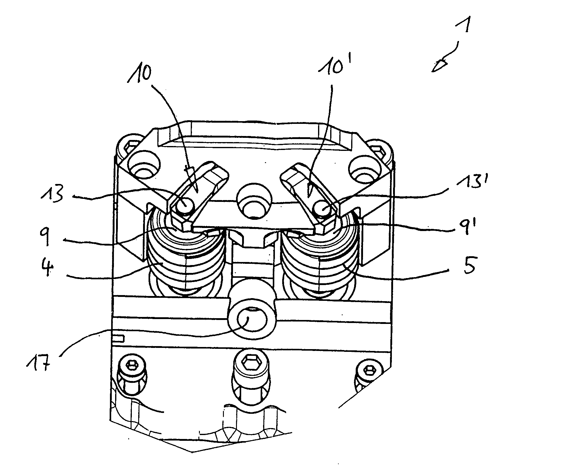
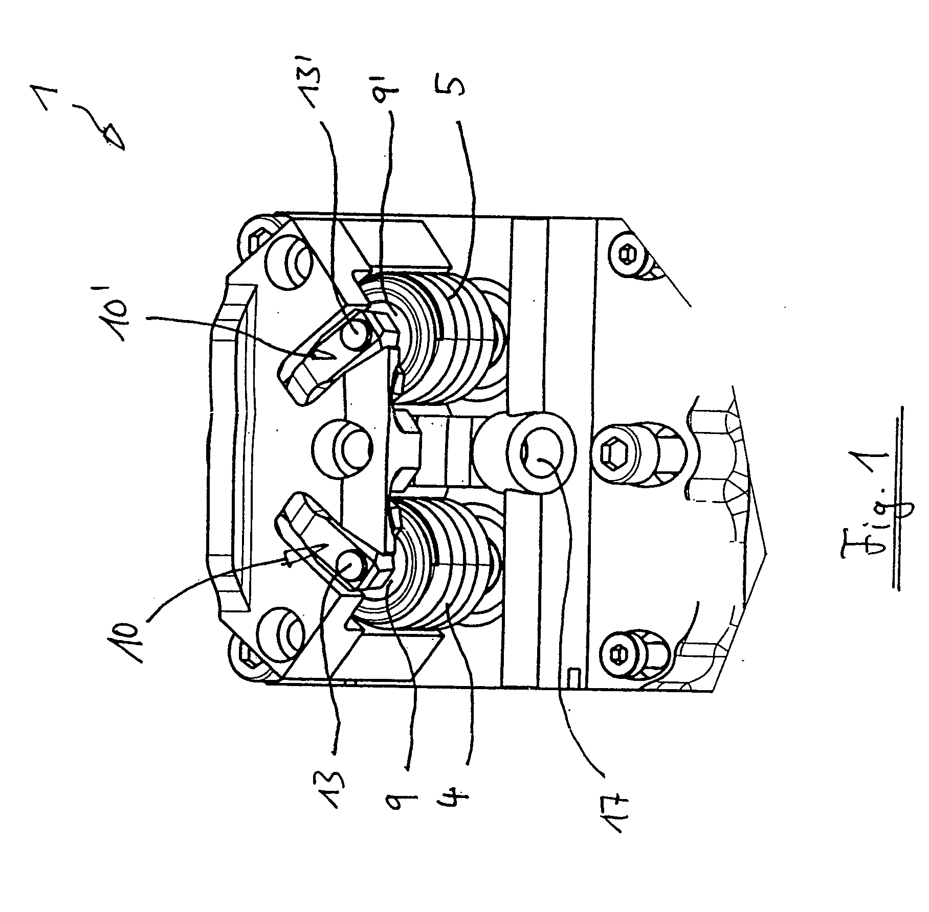
[0026]FIG. 1 illustrates an actuator 1 of an electromagnetic mechanism for actuating two valves of an internal combustion engine, for example, two exhaust valves or two intake valves. (The valves themselves are not shown.) For the valve actuation, a control element formed by an armature rod 2 (compare FIGS. 2, 3) and an armature plate 3 (FIG. 4) is assigned to each valve. One valve spring respectively is provided on each of the two sides of the armature plate, in FIGS. 1 to 3. (Only an upper valve spring is illustrated, which can also be called a valve spring 4, 5 away from the valve.)

[0027] The basic construction of such a control element with two inversely operating valve springs is known. See, for example, from German Patent Document DE 694 09 485 T2, the disclosure of which is incorporated by reference herein, The two valve springs (of which here only the upper valve springs 4, 5 are shown) press the armature rod 2 together with its armature...


PUM


Abstract

An electromagnetic valve actuating mechanism for an internal combustion engine has an axially displaceable control element with an armature plate, for opening or closing a valve. Two solenoids are arranged behind one another in the displacement direction and spaced with respect to one another. One solenoid is arranged on the side of the armature plate close to the valve and the other is on the side away from the valve. Two springs are arranged behind one another in the displacement direction, one of the springs being arranged on the side of the armature plate close to the valve and the other being arranged on the side away from the valve. The control element, which is held in a neutral position when the solenoids are currentless, is deflectable from its neutral position by energizing the solenoids. An adjusting element, which rests on the end of one of the two springs away from the armature plate, is adjustable to change the prestressing of the springs and the location of the neutral position of the control element. The adjusting element, which is displaceably arranged in the displacement direction, is displaceable via an actuating device during the operation of the valve actuating mechanism, for adjusting of the neutral position.

Description

CROSS-REFERENCE TO RELATED APPLICATIONS [0001] This application is a continuation of PCT Application No. PCT / EP2003 / 010330 filed on Sep. 17, 2003, which claims priority to German Application No. 102 48 330.2 filed Oct. 17, 2002.BACKGROUND AND SUMMARY OF THE INVENTION [0002] The present invention relates to an electromagnetic valve actuating mechanism. [0003] An electromagnetic valve actuating mechanism of the generic type is disclosed, for example, from German Patent Document DE 694 09 485 T2. The valve actuating mechanism described there has a displaceable control element or an “armature” with an “armature plate”, for actuating a valve of an internal-combustion engine (that is, an intake valve or an exhaust valve). The armature plate is arranged between two solenoids spaced away from one another in the displacement direction. One solenoid is arranged on the side of the armature plate close to the valve, and the other is arranged on the side away from the valve. In addition, two pre...

Claims


Application Information

Patent Timeline
IPC IPC(8): F01L9/20F16K31/02
CPCF01L2820/01F01L9/04F01L9/20
Inventor MEYER, JOHANNES
Owner BAYERISCHE MOTOREN WERKE AG
Why Eureka
Eureka Blog
Learn More