Electromechanical cable actuator assembly controller

Inactive Publication Date: 2006-12-07
CAPRO LTD
View PDF12 Cites 7 Cited by
  • Summary
  • Abstract
  • Description
  • Claims
  • Application Information

AI Technical Summary

Benefits of technology

[0007] The disclosed vehicle-mounted electromechanical cable actuator assembly combines speed and quiet operation with a high load capacity to impart f

Problems solved by technology

Complex seating systems require complex mechanical motion control mechanisms.
These complex mechanical motion control mechanisms employ latches, levers an

Method used


Image

  • Electromechanical cable actuator assembly controller
  • Electromechanical cable actuator assembly controller
  • Electromechanical cable actuator assembly controller

Examples


Embodiment Construction

[0031] The invention will now be described with reference to the drawing figures, in which like reference numerals refer to like parts throughout.

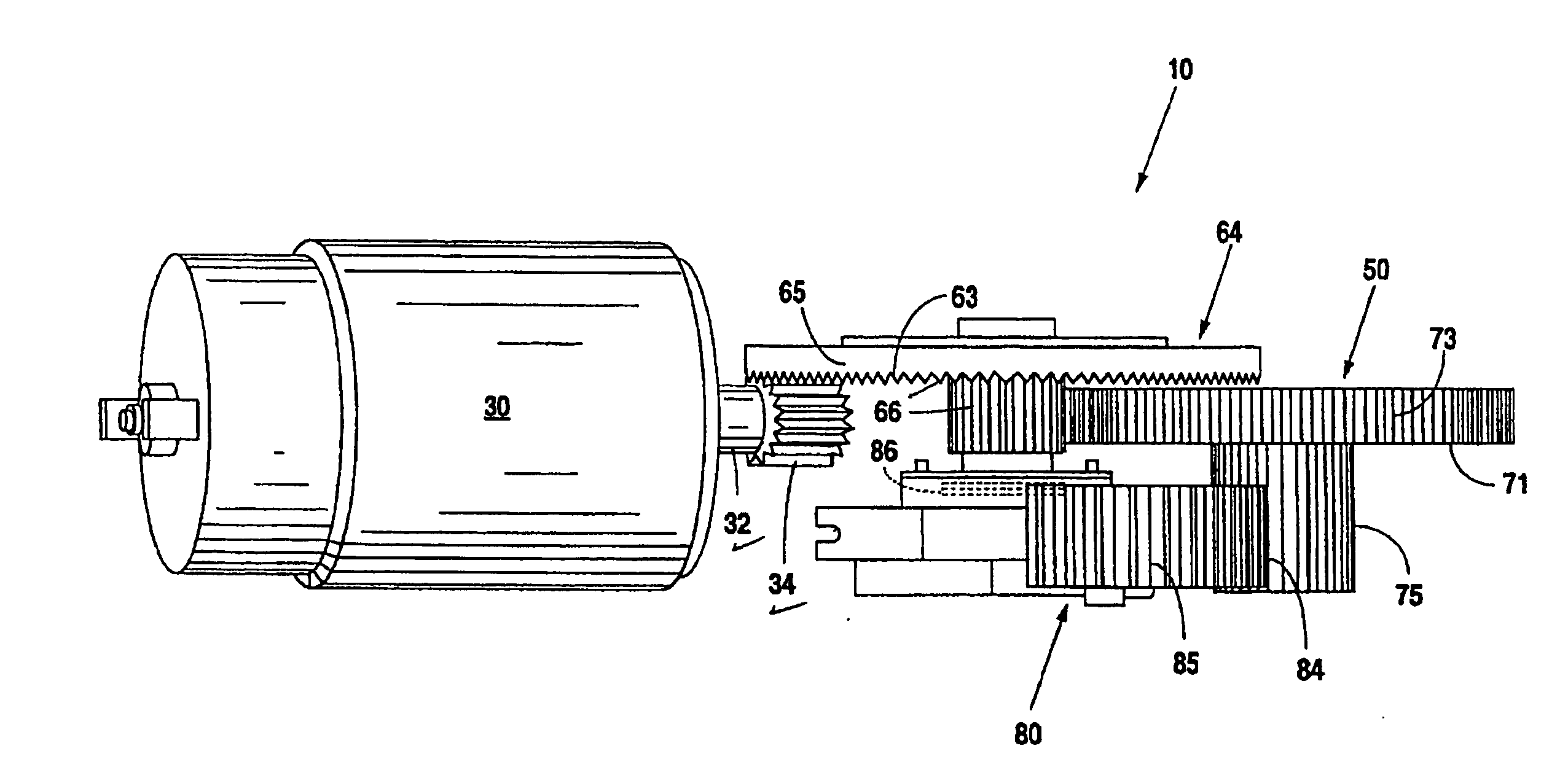
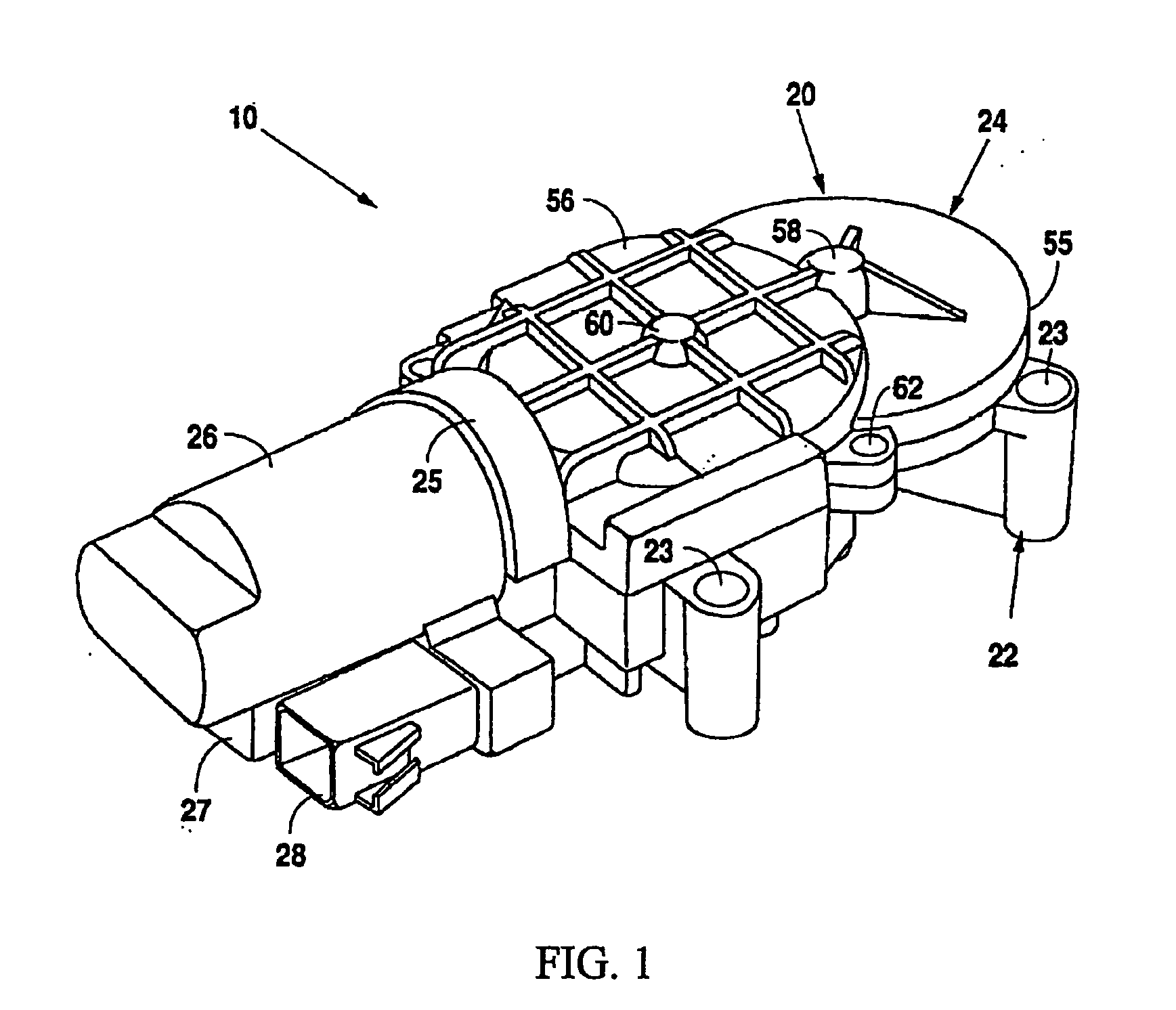
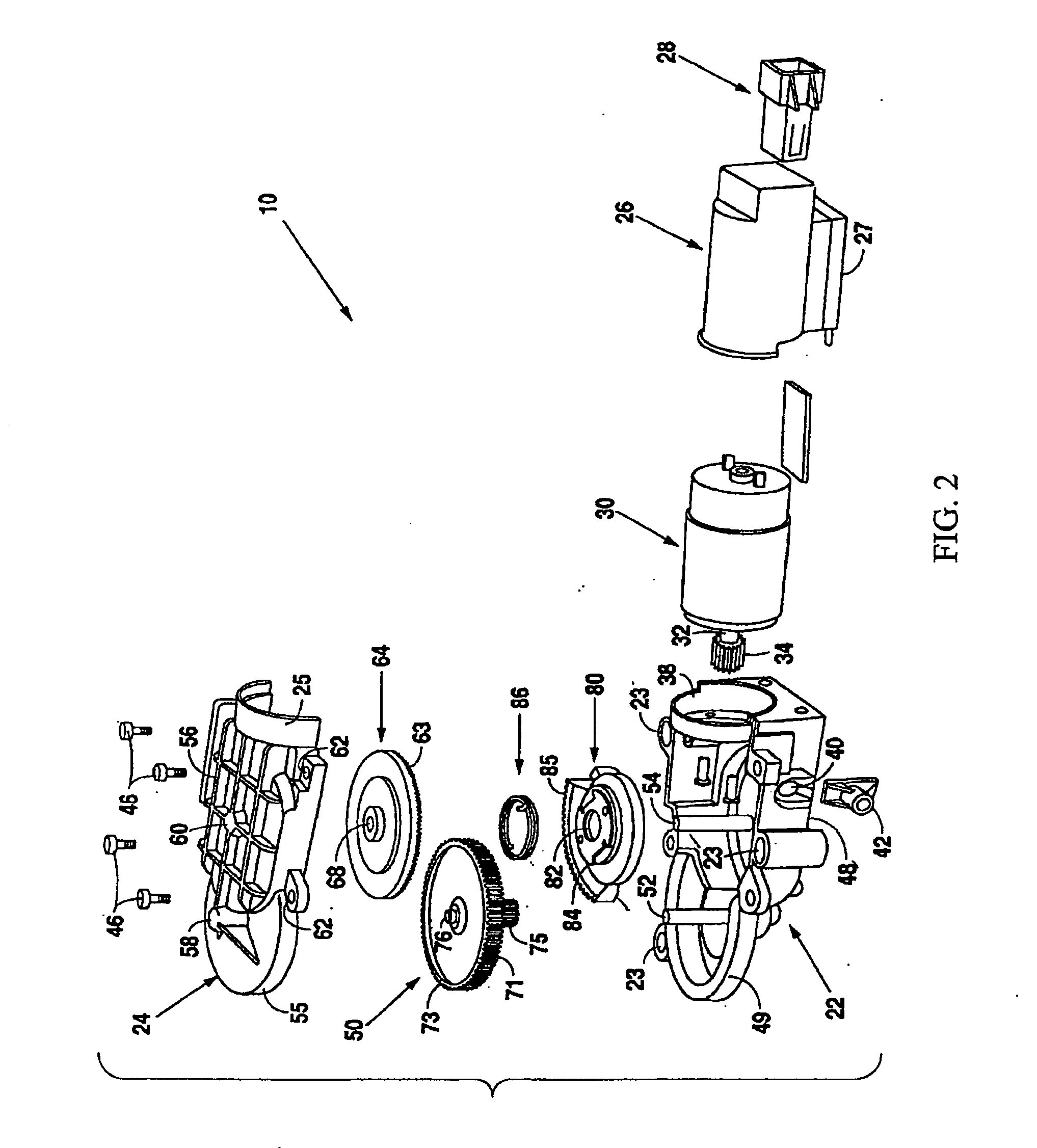
[0032] As will be seen in FIGS. 1, 2, 3, and 4, the electromechanical cable actuator 10 of the present invention is a self-contained device whose size is conducive to allowing its installation in a vehicle. To meet the requirements of automobile manufacturers, the disclosed electromechanical cable actuator 10 must be operable using the available electrical power provided by the electrical system typically found on a passenger vehicle. Specifically, the disclosed electromechanical actuator 10 must operate at a low voltage (specifically, 12 volts in most U.S. passenger vehicles) and have a small current draw (typically, 5 amps maximum). Yet, at the same time, the electromechanical actuator 10 must be able to impart a sufficient level of force on a cable to rapidly operate the mechanical locking portions of various different types of complex...


PUM


Abstract

An electromechanical cable actuator assembly is disclosed, the actuator having a motor, a gear assembly coupled to the motor, a spring-loaded return assembly coupled to the gear assembly being configured to apply a force to the gear assembly to return the electromechanical cable assembly to a first position; and an electronic motor control circuit coupled to the motor. The electronic motor control circuit includes a drive circuit configured to drive the motor in a first direction against the force exerted by the spring assembly and a braking circuit configured to slow the rate of return of the cable assembly to the first position.

Description

[0001] This patent application claims priority from Non-provisional U.S. patent application Ser. No. 11 / 068,579, filed Feb. 28, 2005.FIELD OF THE INVENTION [0002] The present invention pertains to a system for imparting a force on a cable; more particularly the present invention pertains to a system for imparting a force on a cable using a motor, a gear train, and a pulley. The pulley receives rotating force from the motor through the gear train and, when the pulley rotates, force is placed on the cable. The force causes the cable to move a predetermined distance. BACKGROUND OF THE INVENTION [0003] Changing consumer demands for passenger vehicles in the United States have encouraged automobile manufacturers to build multiple-use or utility vehicles that are suitable to carry both passengers and / or cargo. One of the keys to the adaptability of such utility vehicles to carry either passengers and / or cargo is the invention of complex seating systems which enable individual seats to fol...

Claims


Application Information

Patent Timeline
IPC IPC(8): F16C1/22
CPCB60N2/0232B60N2/443Y10T74/20462B60N2002/0236H02K7/1163B60N2/929B60N2/02253B60N2/02246B60N2/02
Inventor COCKERHAM, RAYSAUDER, JOHNRABORN, RON
Owner CAPRO LTD
Why Eureka
Try Eureka