
Bearing having threaded rollers

Active Publication Date: 2021-11-23
DUBUS JEROME
View PDF19 Cites 0 Cited by
  • Summary
  • Abstract
  • Description
  • Claims
  • Application Information

AI Technical Summary

Benefits of technology

The invention is a roller bearing that can be used as an abutment or thrust bearing. It offers an alternative to existing rolling bearings and has excellent load capacity, is more reliable, and is simpler and easier to manufacture and assemble, while being less costly. The threads have self-compensatory action that prevents the rollers from slipping axially, and make it possible to obtain a system having high load capacity with almost no slippage, and have a long life span. The mechanism is also advantageous in that it does not involve any grooves or sets of teeth, and is easy to assemble by screw-fastening.

Problems solved by technology

Conventional rolling bearings include ball bearings, tapered roller bearings, or indeed cylindrical roller bearings, and such conventional bearings are the most widely used because of their low cost, with the drawback of being of large overall size in particular when they are dimensioned to bear high loads.

Method used


Image

  • Bearing having threaded rollers
  • Bearing having threaded rollers

Examples


Embodiment Construction

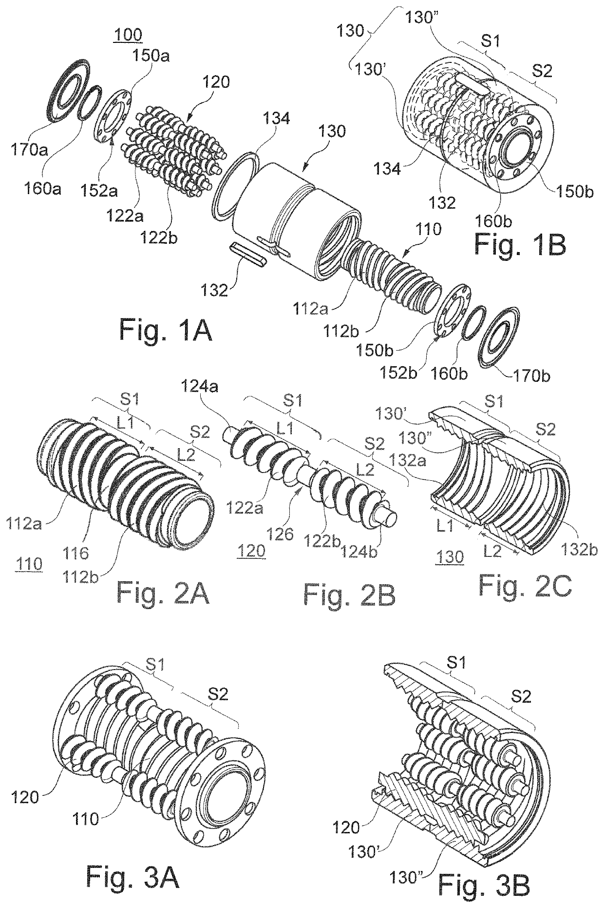
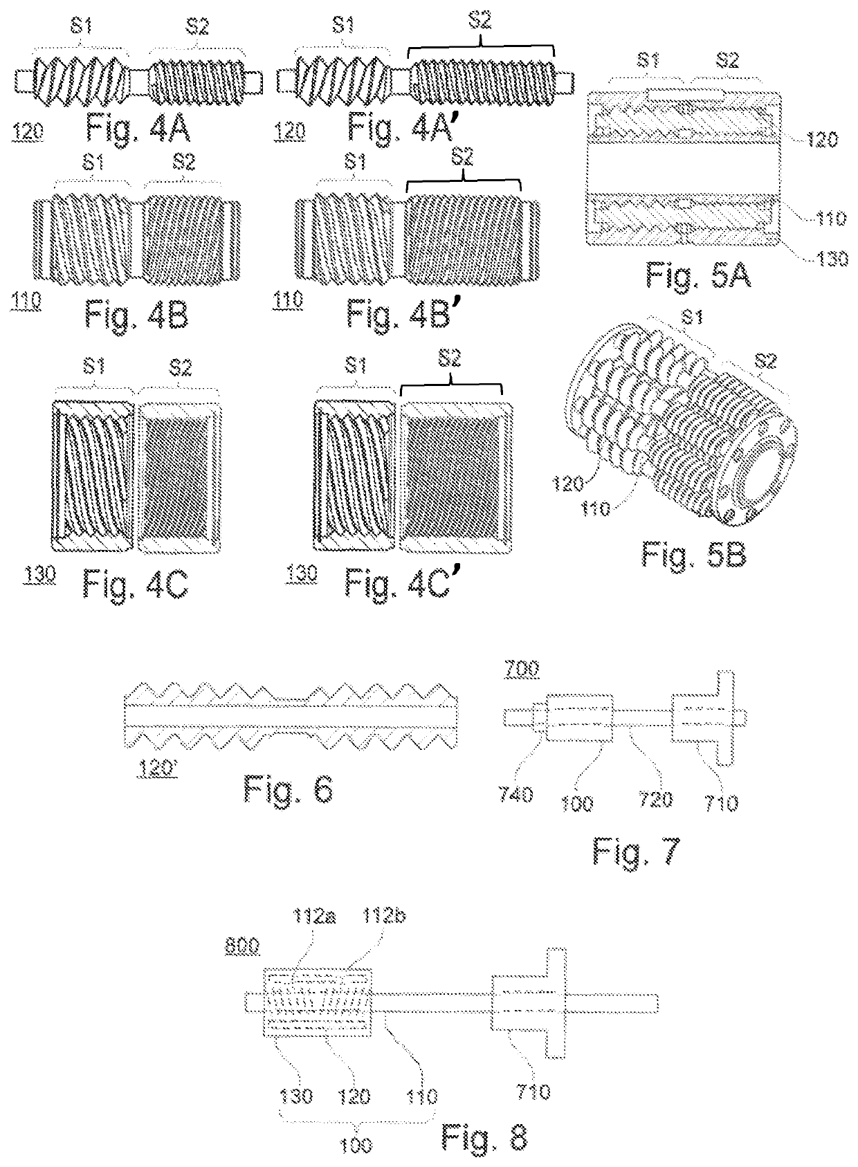
[0034]A rolling bearing mechanism of the invention is shown in FIGS. 1A and 1B, 2A to 2C, 3A and 3B, 4A to 4C, 4A′ to 4C′, 5A and 5B, 6, 7, and 8.

[0035]FIG. 1A shows a particular rolling bearing mechanism, taken by way of example for illustrating the main elements making up a rolling bearing mechanism of the invention.

[0036]It should be understood that neither the invention nor the present embodiment are limited to this particular situation.

[0037]As shown in FIG. 1A, a rolling bearing mechanism 100 may comprise a rod 110, an outer ring 130 disposed around the rod, surrounding it coaxially, and a plurality of rollers 120 interposed between the rod and the outer ring and having their longitudinal axes parallel to the longitudinal axes of the rings.

[0038]The rod 110 may be solid or hollow, and when it is hollow, it may also be referred to as an “inner ring”; the rod 110 may extend longitudinally on either side of the outer ring 130, e.g. as in the device shown in FIG. 8.

[0039]As shown ...


PUM


Abstract

A rolling bearing mechanism comprising a rod (110), an outer ring (130) surrounding the rod coaxially, and rollers (120) interposed between the rod (110) and the outer ring (130), with the rod, the outer ring, and the rollers each having a respective right-handed thread and a respective left-handed thread, the left-handed threads (122a) of the rollers meshing with the right-handed thread (112a) of the rod and with the left-handed thread of the outer ring, and the right-handed threads (122b) of the rollers (120) meshing with the left-handed thread (112b) of the rod (110) and with the right-handed thread of the outer ring (130).

Description

CROSS REFERENCE TO RELATED APPLICATIONS[0001]This application is the U.S. National Stage of PCT / FR2018 / 053013 filed on Nov. 27, 2018, which application claims priority under 35 USC § 119 to French Patent Application No. 17 61592 filed on Dec. 4, 2017. Both of these applications are hereby incorporated by reference in their entirety.TECHNICAL FIELD[0002]The invention relates to the field of rolling bearings, such a bearing being a mechanism that supports and guides an assembly in rotation.BACKGROUND OF THE INVENTION[0003]Conventional rolling bearings include ball bearings, tapered roller bearings, or indeed cylindrical roller bearings, and such conventional bearings are the most widely used because of their low cost, with the drawback of being of large overall size in particular when they are dimensioned to bear high loads.[0004]Rolling bearings exist that are based on systems of rollers having screw threads or grooves and that are more costly than conventional bearings but that have...

Claims


Application Information

Patent Timeline
IPC IPC(8): F16C19/36F16C33/30F16C33/36F16C33/58
CPCF16C19/36F16C33/306F16C33/363F16C33/581F16C33/585F16C2300/00F16C19/50F16C33/36F16C33/58
Inventor DUBUS, JÉROME
Owner DUBUS JEROME
Learn More