Helical head restraint guide

a head restraint and guide technology, applied in the field of motor vehicles, can solve the problems of difficult installation, difficult removal from the back frame, and costly approach to installing head restraint guides, and achieve the effect of convenient installation and removal

Inactive Publication Date: 2005-08-18
LEAR CORP
View PDF10 Cites 21 Cited by
  • Summary
  • Abstract
  • Description
  • Claims
  • Application Information

AI Technical Summary

Benefits of technology

[0016] This invention has many features that are unique when compared to existing art. First, the stems of this invention are installed before the seat is foamed and trimmed. This facilitates installation and removal. Typically, head restraint guides are installed after foaming and trimming leading to blind installation and frequent damage. Second, the multi-point socket head allows the head restraint guide assembly to be torqued down with a tool instead of the usual way of being thrust or hammered into seat frame. Third, the helix, multi-point socket head, open wrench flats, or internal torx head, and crush ribs facilitate tight installation to eliminate the chuck between the head restraint guide assembly and the seat frame. Typical head restraint guides have significant chuck.

Problems solved by technology

The problem with installing the head restraint guides after the seat is foamed and trimmed is that it is then difficult to install and then if necessary, difficult to remove from the back frame.
This can be a costly approach to installing head restraint guides.
Another problem that typical head restraint guide assemblies encounter is that they may only be installed in exactly one manner.
As a result, one may encounter difficulty in finding replacement pieces for repairs and can add more time to installation.
Costs also increase if parts are installed or repaired improperly due to the installer's confusion.
Another problem is that typical head restraint guides have chuck between the guide and seatback and thereby increase the chuck of head restraint assembly to seat frame.
This can cause significant rattling noises between the head restraint assembly to the seat frame.
For safety reasons, the head restraint is also not able to be removed from the guide without the use of a tool.

Method used


Image

  • Helical head restraint guide
  • Helical head restraint guide
  • Helical head restraint guide

Examples


Embodiment Construction

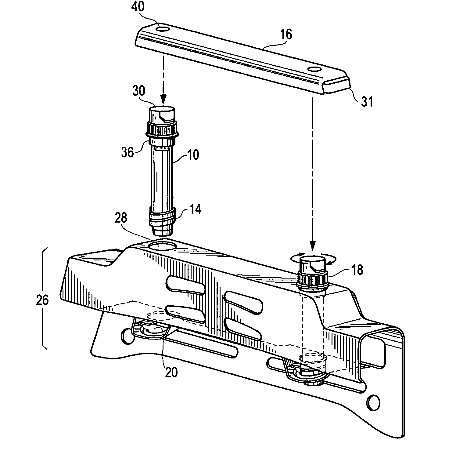
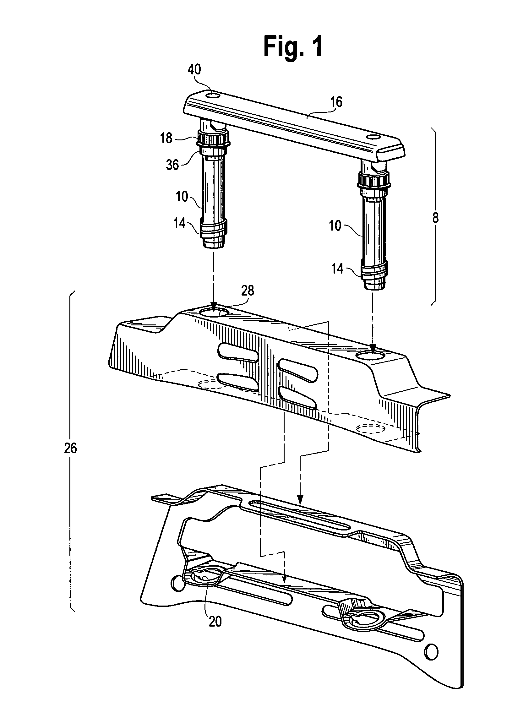
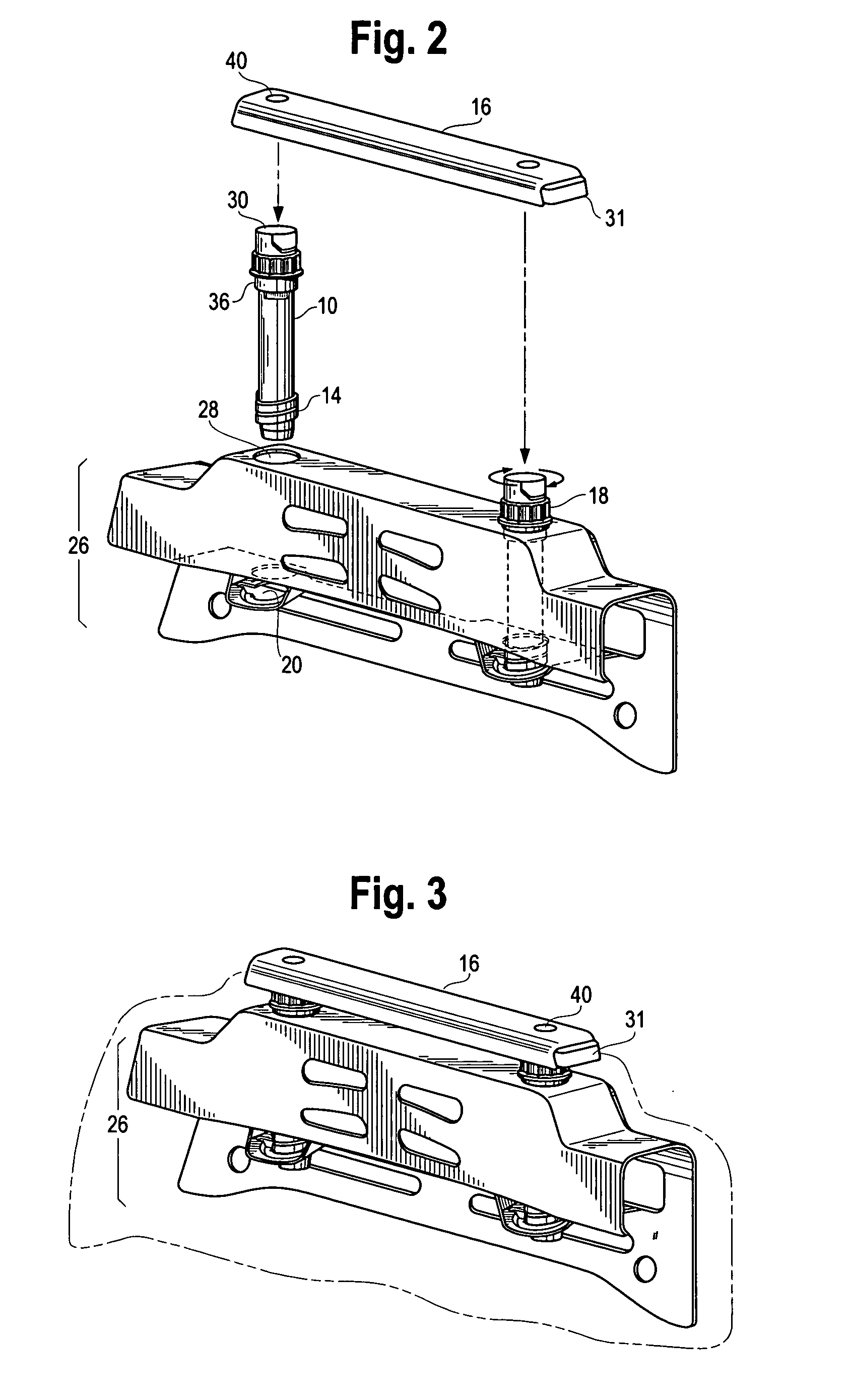
[0028] In one of the preferred embodiments, this dual locked, torqued, error proofed for installation, chuck free helical head restraint guide comprises a head restraint guide assembly 8 further comprising at least two stems 10, a button sub-assembly 12 and bezel 16; a seat for a motor vehicle (not shown) comprising an upper cross member 26 of the back frame; and a head restraint assembly 38 further comprising head restraint posts 32 and a head restraint pad 34.

[0029] The stems 10 are identical to one another and comprise a helix 14 at one end and a multi-point socket head 18, open wrench flats 30, or and / or internal torx head and crush ribs 36 at the other end. The crush ribs 36 enable a tight fit between the stems 10 and the upper hole 28 in the upper cross member 26 of the back frame. The upper cross member 26 of the back frame of the seat has lower openings 20. These lower openings 20 corresponds to the helix 14 on each of the stems 10. These lower openings 20 accept the helix ...


PUM


Abstract

A torqued, error proofed for installation, chuck free helical head restraint guide that includes a head restraint guide assembly with at least two stems, a button sub assembly, and a bezel. The stems include a helix at one end of each stem and a multi-point socket head, an open wrench flat, and/or an internal torx head and crush ribs at the other end. The head restraint guide also includes a motor vehicle passenger seat that includes an upper cross member of a back frame with upper and lower openings. The head restraint guide further includes a head restraint assembly with head restraint posts and a head restraint pad.

Description

FIELD OF INVENTION [0001] This invention relates to head restraints in motor vehicles. More specifically, it relates to a head restraint guide that is torqued, error-proofed for installation, and chuck free. BACKGROUND OF INVENTION [0002] Today, most, if not all, motor vehicles come with seats equipped with head restraints. Head restraints provide not only comfort for riders but also serve the function of protecting an occupant's head and neck in case of an accident. [0003] Head restraint systems typically have head restraint guides within the back frame of the seat. Typical head restraint guides are installed after the seatback is foamed and trimmed. The problem with installing the head restraint guides after the seat is foamed and trimmed is that it is then difficult to install and then if necessary, difficult to remove from the back frame. This can be a costly approach to installing head restraint guides. [0004] Another problem that typical head restraint guide assemblies encount...

Claims


Application Information

Patent Timeline
Patent Type & Authority Applications(United States)
IPC IPC(8): A47C1/10B60N2/48B60R22/28
CPCB60N2002/4897B60N2/48B60N2/80B60N2/897
Inventor YETUKURI, NAGARJUNHUMER, MLADENFARGUHAR, MARKSMALLWOOD, DALE
Owner LEAR CORP
Why Eureka
Try Eureka