Lens centering mechanism, lens apparatus and imaging apparatus

a technology of lens and centering mechanism, which is applied in the direction of camera focusing arrangement, printers, instruments, etc., can solve the problems of obstructing the centering operation, reducing the overall size of the apparatus, and the risk of the image of the component parts being taken into the chart image, so as to facilitate the optimal adjustment of the tilt, facilitate the centering operation, and pick up satisfactorily

Inactive Publication Date: 2005-08-18
SONY CORP
View PDF6 Cites 13 Cited by
  • Summary
  • Abstract
  • Description
  • Claims
  • Application Information

AI Technical Summary

Benefits of technology

[0017] In view of the above depicted state of the related art, it is an object of the present invention to provide a lens centering mechanism which enables facilitated and optimized centering of the lens held by the lens holding member.
[0018] It is another object of the present invention to provide a lens apparatus in which, by facilitated optimized centering of the lens held by the lens holding member, the optical performance of each lens held by main body unit of the lens barrel may be maintained, and in which, by reducing the number of component parts and the number of the assembling steps, the apparatus may be further reduced in size and cost.
[0019] It is yet another object of the present invention to provide an imaging apparatus in which, by facilitated optimized centering of the lens held by the lens holding member, the optical performance of each lens held by the lens holding member may be maintained, and an image of an object formed by plural lenses may be optimally picked up by a solid-state imaging device, and in which, by reducing the number of component parts and the number of the assembling steps, the apparatus may be further reduced in size and cost.

Problems solved by technology

In particular, on the front surface side of the main body unit of the lens barrel, the outer shape of the main body unit of the lens barrel is significantly swollen out with respect to the lens held by the lens holding member, thus leading to a significant demerit in reducing the overall size of the apparatus.
However, with these lens apparatus 200, 300, in which the set screws or adjustment screws are tightened in a direction parallel to the optical axis, from a position proximate to the front side lens of the lens holding member, an image of a jig for tightening the screws or the operator=s hand tends to be taken into an image of the chart at the time of adjustment, thus obstructing the centering operation.
On the other hand, with the above-described lens apparatus 200, 300, in which the set screws or the adjustment screws are mounted in a direction towards the optical axis, at the time of adjustment, these screws tend to be intruded into the inside of the main body unit of the lens barrel, thus giving rise to a risk of the image of the component parts being taken into the chart image.
On the other hand, if, as described in the Reference Cited 1, the lens tilt is adjusted as offset pins provided at two outer peripheral points are rotated, with a reference pin provided at a point on the outer rim as a fulcrum point, the lens is displaced in its entirety in a direction towards the optical axis, thus possibly affecting the optical performance.
In addition, with the offset pins fitted in elongated holes, it is necessary to provide a clearance, from the aspect of designing, with the result that the overall lens may possibly suffer from backlash.
If, as described in the above Reference Cited 2, the movable lens barrel is to be moved by a conjoint operation of a guide groove formed in a guide tube, a cam groove formed in a cam cylinder and a cam pin provided at a point of intersection of the guide groove and the cam groove, the cam pin is fixedly threaded to the movable lens barrel, thus leading to significant demerit in reducing the number of component parts and the number of operating steps.
Moreover, there is no limitation imposed on the rotation about the optical axis of the movable lens barrel, thus giving rise to a risk that the lens not only tends to be shifted along the optical axis but also tends to be rotated about its optical axis.
There is also a risk that, except if the cam pin is fixed after adjustment, the cam pin tends to be rotated during use such that it becomes impossible to maintain the adjusted state.

Method used


Image

  • Lens centering mechanism, lens apparatus and imaging apparatus
  • Lens centering mechanism, lens apparatus and imaging apparatus
  • Lens centering mechanism, lens apparatus and imaging apparatus

Examples


Embodiment Construction

[0054] Referring to the drawings, a lens centering mechanism, a lens apparatus and an imaging apparatus, embodying the present invention, will be explained in detail.

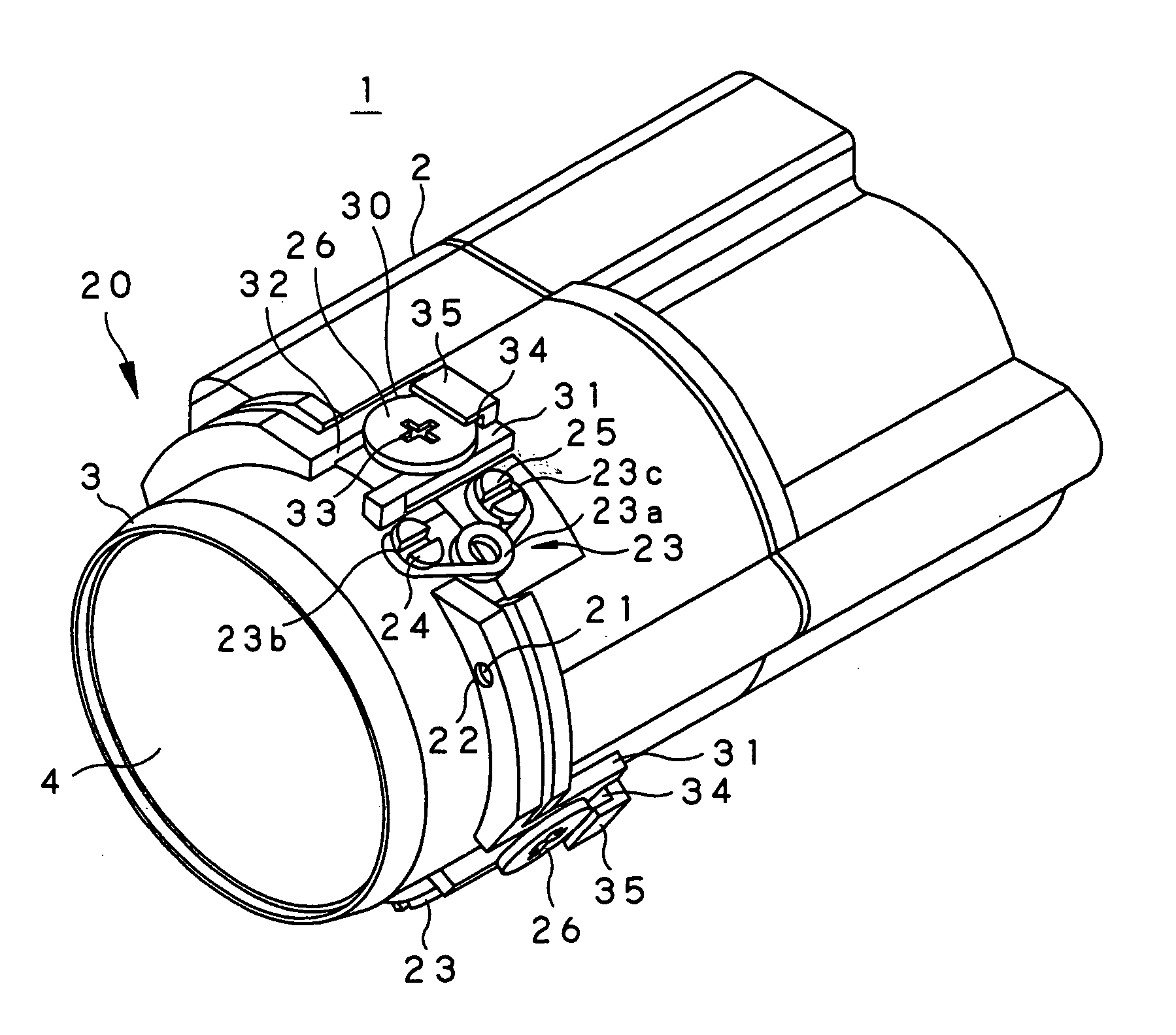
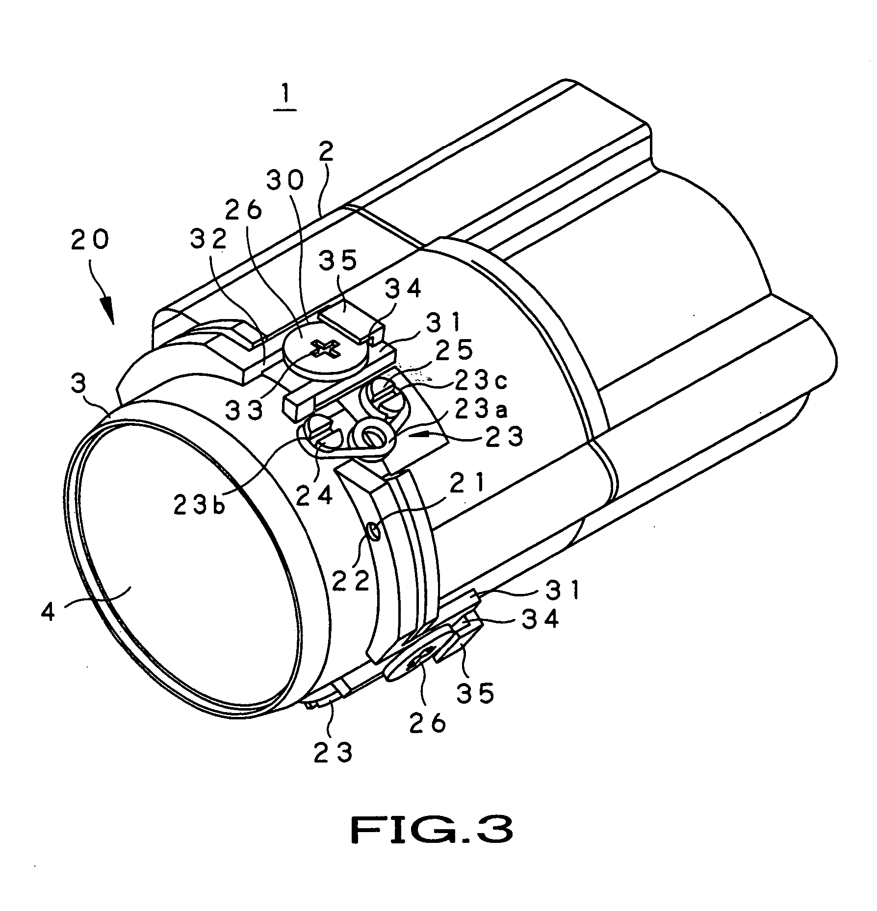
[0055] Referring first to FIG. 3, a lens apparatus 1, embodying the present invention, is a so-called lens barrel, configured for forming an image of an object by a plural number of lenses mounted on a common optical axis within a main body unit of the lens barrel 2. A solid-state imaging device for photographing an image of the object, formed by the plural number of lenses, is mounted on the back surface of the lens barrel, for constructing an imaging apparatus embodying the present invention.

[0056] Specifically, the main body unit of the lens barrel 2 is formed to substantially a cylindrical shape from a black resin material, exhibiting certain strength, mass-producibility and light shielding properties, for example, a polycarbonate resin containing glass fibers. On the front side of the main body unit of the lens b...


PUM


Abstract

A lens held by a lens holding member is to be centered easily correctly. To this end, a guide pin 21 is inserted into a guide hole 22 for positioning the lens holding member 3 with respect to the main body unit of the lens barrel 2 in a plane perpendicular to the optical axis of the lens 4 and for mounting the lens holding member for movement in a direction along the optical axis. If, in this state, each of adjustment pins 26, rotationally mounted on at least three sites on the outer peripheral surface of the main body unit of the lens barrel 2, is rotated, an offset portion 29 of the adjustment pin, offset relative to the center of rotation of the adjustment pin, is rotated, as the offset portion is engaged in an engagement hole 32 of the lens holding member 3, so that the lens holding member 3 on each site is displaced in the direction along the optical axis to adjust the tilt of the lens 4 held by the lens holding member 3.

Description

BACKGROUND OF THE INVENTION [0001] 1. Field of the Invention [0002] This invention relates to a lens centering mechanism for centering a lens when a lens holding member holding a lens is mounted to a main body unit of a lens barrel, a lens apparatus, and to an imaging apparatus having such lens centering mechanism. [0003] 2. Description of Related Art [0004] Up to now, there have been used lens apparatus in which an image of an object is formed by plural lenses arranged in a main body unit of the lens barrel as optical axes thereof are aligned with one another. There have also been used imaging apparatus, such as a digital still camera or a digital video camera, for receiving an image of an object, formed by such lens apparatus, by a solid-state imaging device, such as a CCD (charge-coupled device) or CMOS (complementary metal-oxide semiconductor) device, and for outputting electrical signals, obtained on photo-electric conversion of light received by the solid-state imaging device,...

Claims


Application Information

Patent Timeline
Patent Type & Authority Applications(United States)
IPC IPC(8): G02B7/02G02B27/62
CPCG02B7/023G02B13/009H04N17/002G03F7/70825H04N5/2254G02B27/62H04N23/55
Inventor ORIMO, SHINICHIMORI, HIROYUKI
Owner SONY CORP
Why Eureka
Try Eureka