Digital subscriber line driver

a subscriber line and driver technology, applied in the field of communications systems, can solve the problems of increasing the peak transmit signal power of the peak transmit signal, affecting the performance of the dsl communication device, and presenting high impedance to the communication device coupled to the lin

Inactive Publication Date: 2005-08-18
DZS LLC
View PDF34 Cites 18 Cited by
  • Summary
  • Abstract
  • Description
  • Claims
  • Application Information

AI Technical Summary

Problems solved by technology

The subscriber loop includes two wires, which are commonly referred to as “tip” and “ring.” Unfortunately, the subscriber loop may also include “bridged taps,” which are unterminated subscriber loops and which present high impedance to communication devices coupled to the line.
However, even the slowest DSL communications devices achieve data rates far in excess of conventional point-to-point modems.
Unfortunately, this boost in power increases the peak transmit signal power.
The peak signal power in conventional DMT transmitters is sufficiently high to cause saturation or clipping of the transmitter in normal operation, thus preventing the use of DMT based systems in dense central site locations.
Coders such as these induce a significant amount of throughput delay and are unsuitable for multi-point communication environments.
Another limitation of DMT is a lack of transmit equalization or pre-emphasis.
Unfortunately, this assumption disregards the unique impedance of each subscriber loop and may result in a non-flat transmit spectrum on the tip and ring wires of the subscriber loop.
Unfortunately, this tone powers variation results in spectrum management difficulties.
Unfortunately, this results in the undesirable situation in which some carriers will be 2.5 dB hotter than necessary in certain spectral bands, resulting in undesirable cross-talk, while other carrier tones are switched off completely.
Cross talk between wire pairs in cable bundles or in dense equipment cabinets is the major contributor to degradation in DSL networks.
While currently allowed, a boost of 2.5 dB in power will effectively lower channel capacity by 2.5 dB on neighboring wire pairs, thereby nullifying any true gain that may have been anticipated.

Method used


Image

  • Digital subscriber line driver
  • Digital subscriber line driver
  • Digital subscriber line driver

Examples


Embodiment Construction

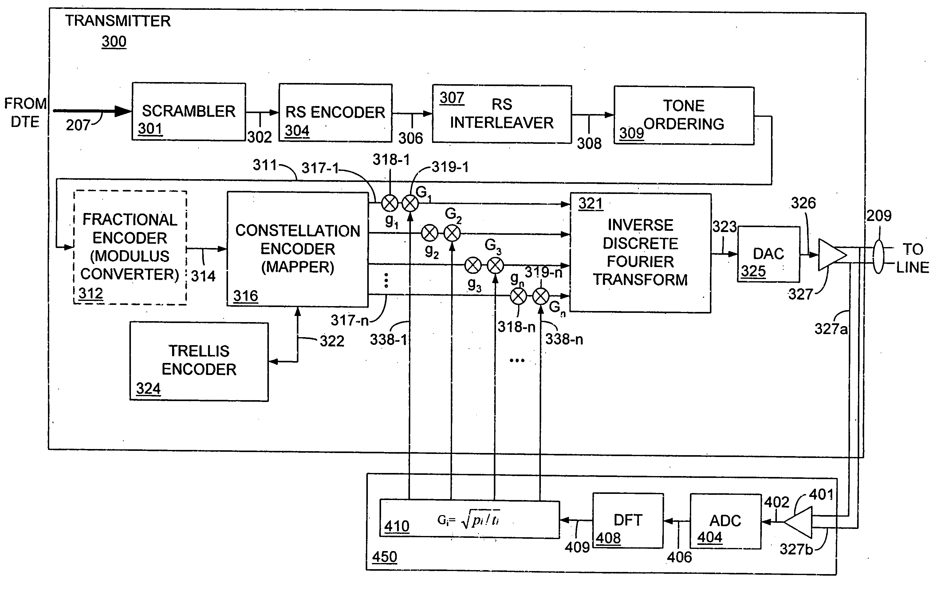
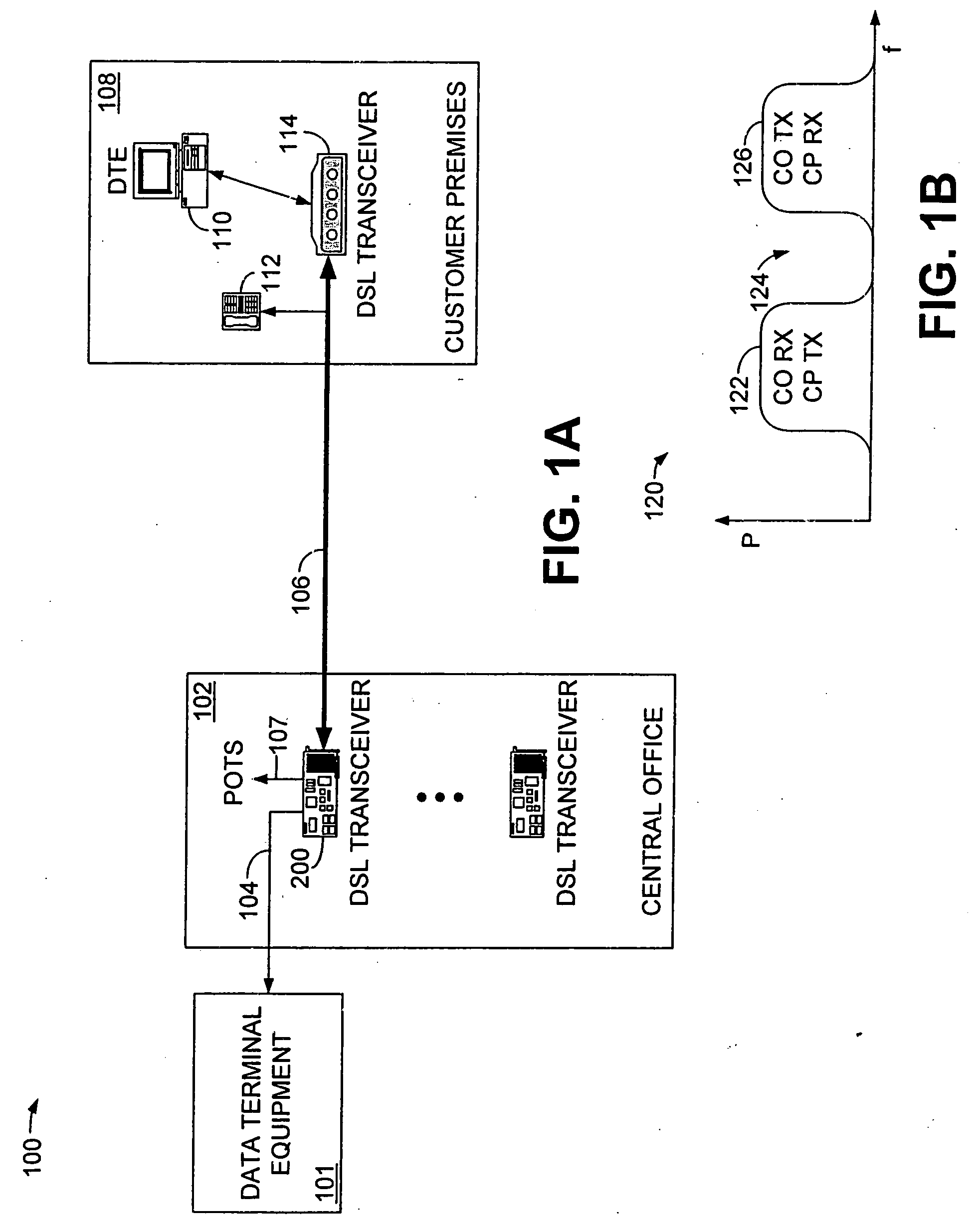
[0022] Although described with particular reference to an asymmetric digital subscriber line (ADSL) communication system using DMT modulation, the digital subscriber line driver of the invention can be implemented in any communication system.

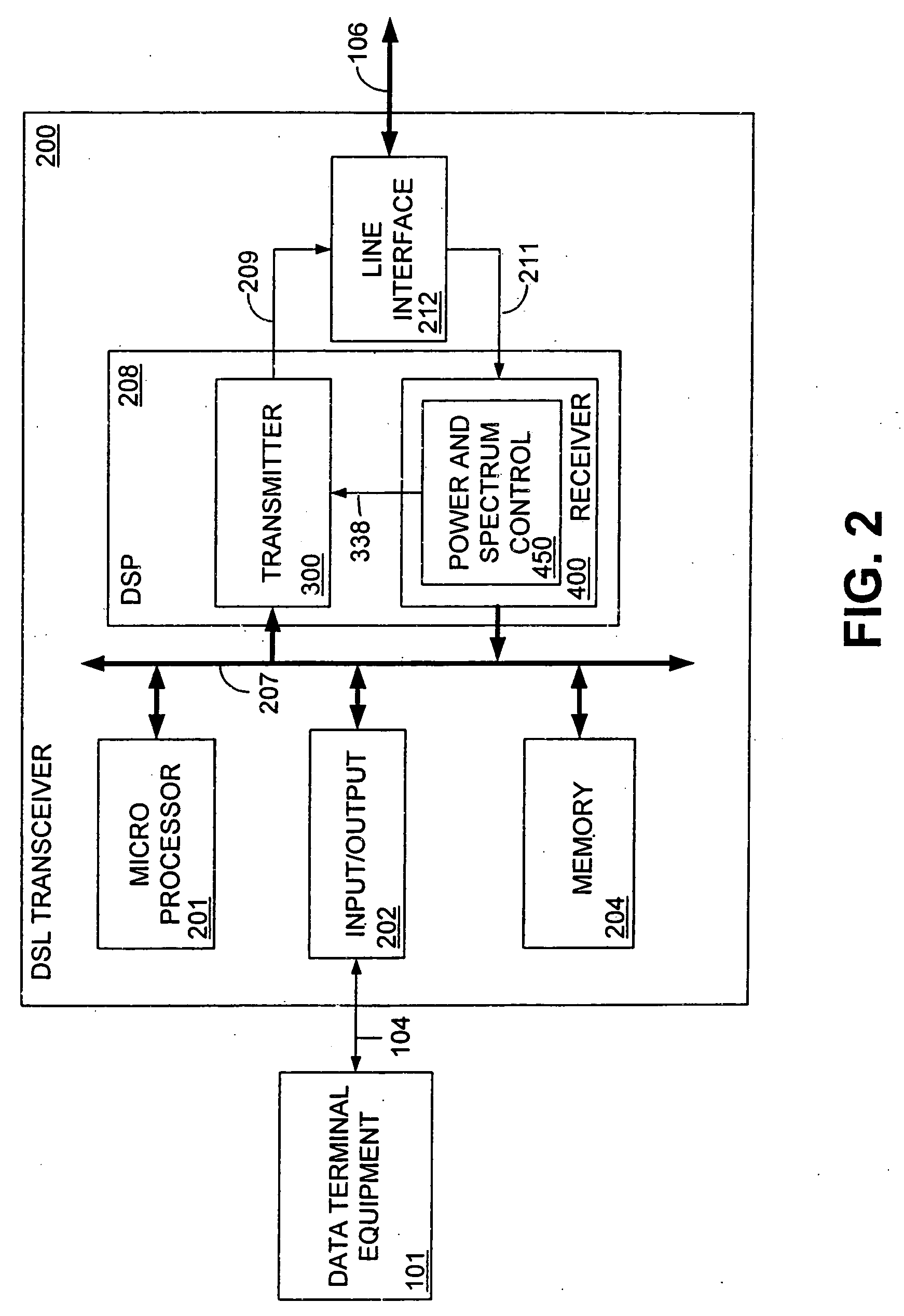
[0023] Furthermore, the digital subscriber line driver can be implemented in software, hardware, or a combination thereof. In a preferred embodiment(s), selected portions of the digital subscriber line driver are implemented in hardware and software. The hardware portion of the invention can be implemented using specialized hardware logic. The software portion can be stored in a memory and be executed by a suitable instruction execution system (microprocessor). The hardware implementation of the digital subscriber line driver can include any or a combination of the following technologies, which are all well known in the art: a discrete logic circuit(s) having logic gates for implementing logic functions upon data signals, an application specifi...


PUM


Abstract

A digital subscriber line (DSL) driver allows a transmitter to monitor its own transmit spectrum at the subscriber loop and adjust the transmit spectrum based on detected line conditions, affected by the presence of bridged taps or any other impedance variations. The transmit spectrum is preferably equalized so that all carriers, or tones, transmit using the same power and exhibit the same margin. The invention is applicable to DMT and single carrier modulation formats.

Description

CROSS-REFERENCE TO RELATED APPLICATIONS [0001] This application is a continuation of application Ser. No. 09 / 733,841, filed Dec. 7, 2000, which claims the benefit of U.S. Provisional Application No. 60 / 170,988, filed Dec. 15, 1999. These applications are entirely incorporated herein by reference.TECHNICAL FIELD [0002] The present invention relates generally to communications systems, and more particularly, to a subscriber line driver for a digital subscriber line (DSL) communications system. BACKGROUND OF THE INVENTION [0003] Data communication typically occurs as the transfer of information from one communication device to another. This is typically accomplished by the use of a modem located at each communication endpoint. In the past, the term modem denoted a piece of communication apparatus that performed a modulation and demodulation function, hence the term “modem”. Today, the term modem is typically used to denote any piece of communication apparatus that enables the transfer ...

Claims


Application Information

Patent Timeline
Patent Type & Authority Applications(United States)
IPC IPC(8): H04B1/38H04K1/10H04L25/03H04L27/26
CPCH04L25/03343H04L2025/03414H04L27/2626
Inventor BETTS, WILLIAM L.
Owner DZS LLC
Why Eureka
Try Eureka