Wind turbine blade with carbon fibre tip

a carbon fibre tip and wind turbine technology, applied in the field of wind turbine blades, can solve the problems of high dead load moment, high fatigue resistance, increased problem with the length of the blade, etc., and achieve the effect of reducing the load on the turbine hub, reducing the weight, and reducing the dead load momen

Inactive Publication Date: 2005-08-18
LM GLASSFIBER
View PDF6 Cites 25 Cited by
  • Summary
  • Abstract
  • Description
  • Claims
  • Application Information

AI Technical Summary

Benefits of technology

This patent describes a new design for wind turbine blades that reduces their weight by dividing them into two parts: one made of fiber reinforced plastic (FRP) and another made of carbon fiber reinforced plastic (CFRP). By doing this, the amount of materials needed towards the edges of the blade are minimized which results in lower costs and less stress placed on the turbine's hub. Additionally, the CFRP can have its strength improved without adding extra cost or complexity. Overall, these designs provide greater efficiency and durability while also being easier and cheaper to manufacture.

Problems solved by technology

The technical problem addressed in this patent text relates to reducing the dead load moments on fiberglass blades while maintaining their strength for longer periods of use.

Method used


Image

  • Wind turbine blade with carbon fibre tip
  • Wind turbine blade with carbon fibre tip
  • Wind turbine blade with carbon fibre tip

Examples


Embodiment Construction

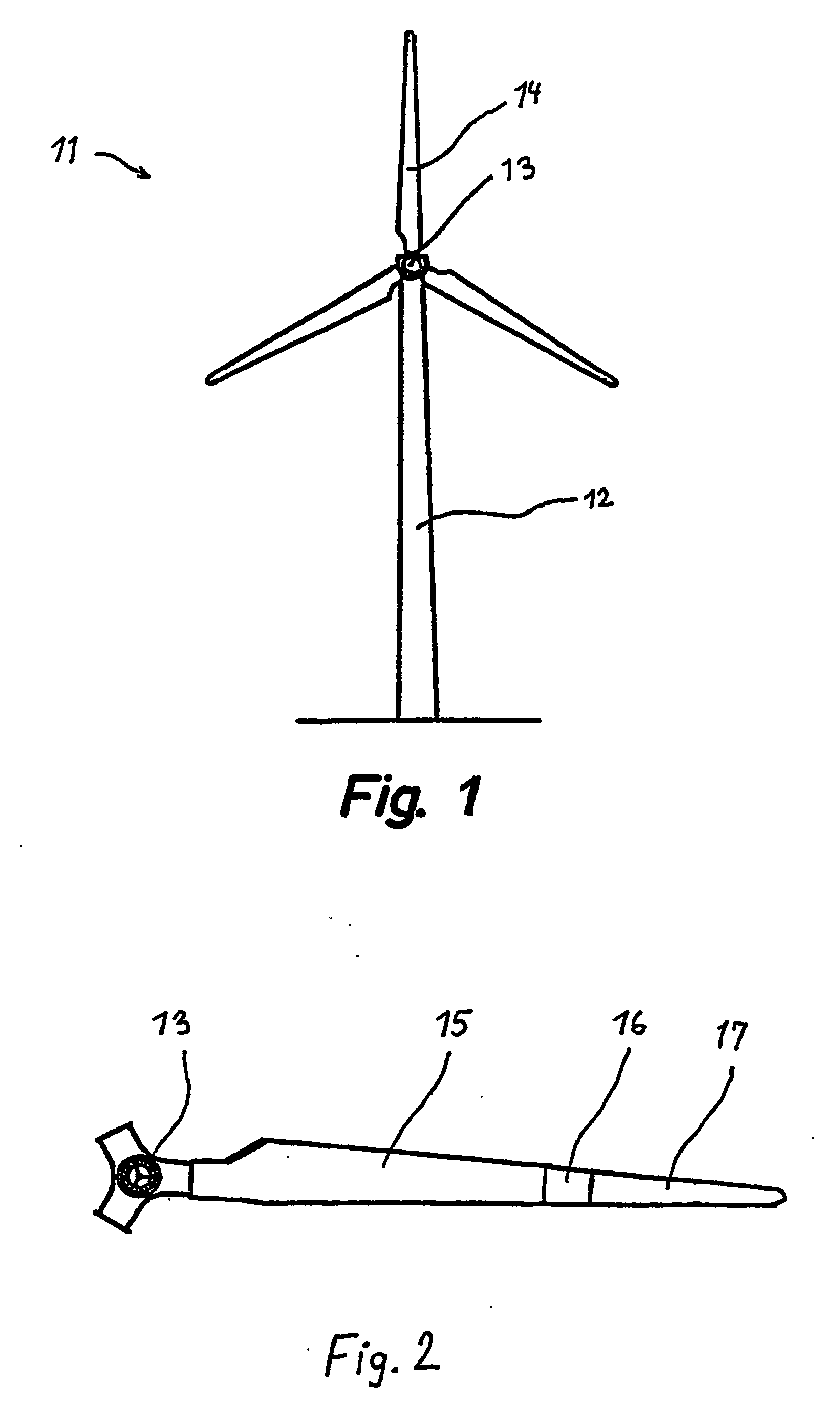
[0030]FIG. 1 shows a modern wind turbine including a tower 12 with a hub 13 and three wind turbine blades 14 extending from the hub.

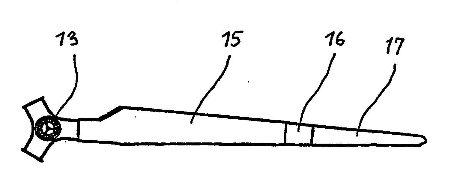
[0031]FIG. 2 illustrates an embodiment of a wind turbine blade according to the invention, in which an inner end portion 15 including the blade root is made substantially from fibre glass-reinforced polymer, and in which an outer end portion 17 including the blade tip is made substantially from carbon fibre-reinforced polymer. Bordering on the inner end portion 15 the outer end portion 17 includes a transition zone 16, in which the carbon fibres are gradually replaced by glass fibres such that a gradual change in the stiffness of the blade is obtained.

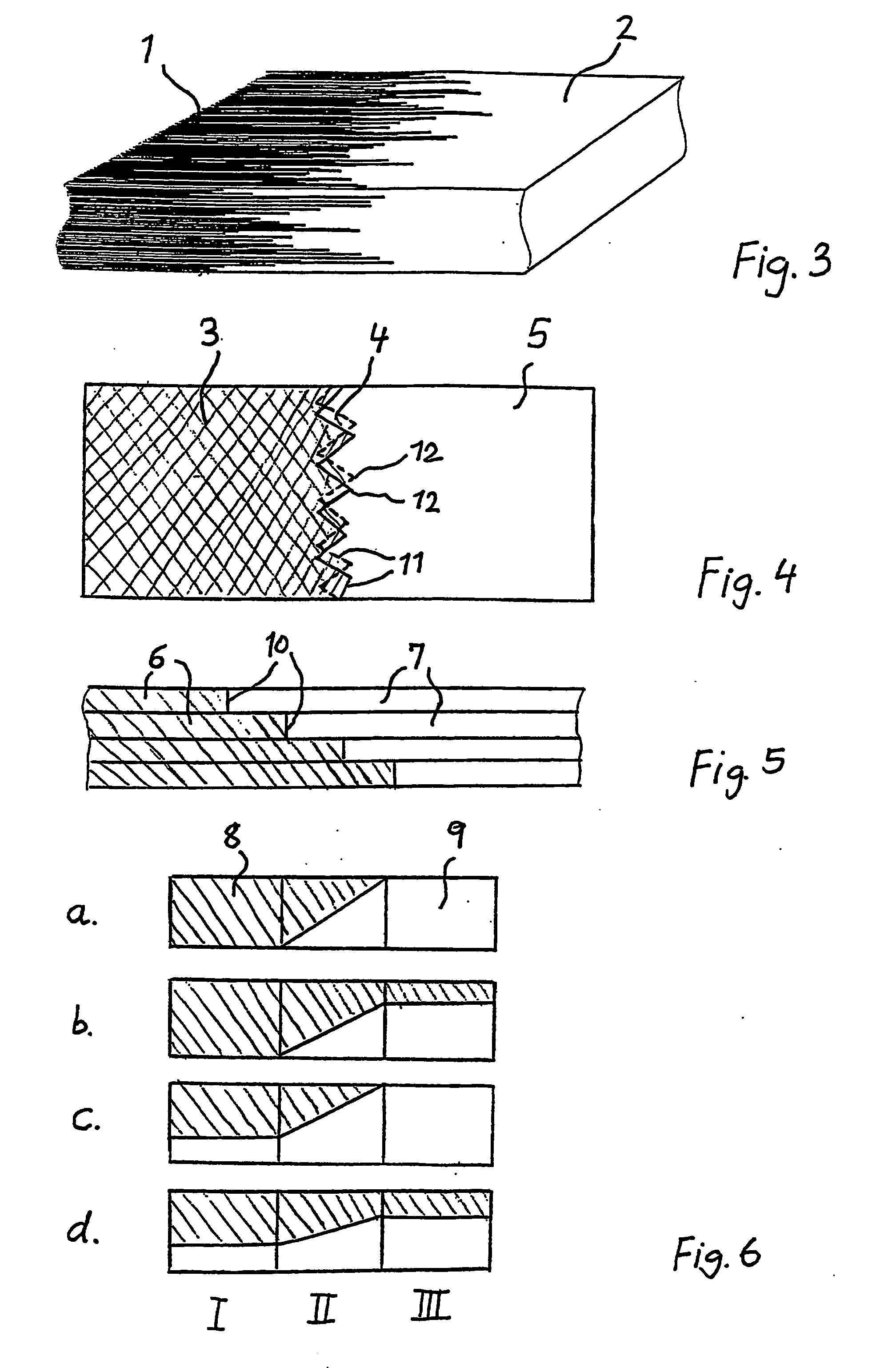
[0032]FIG. 3 is a sectional view of the transition zone, in which the quantitative ratio of carbon fibres to glass fibres gradually changes. The carbon fibres 1 extend from the left-hand side of the sectional view in form of bundles or single-fibres of different lengths. The glass fibres 2 are not visibl...


PUM


Abstract

The invention relates to a wind turbine blade (14) of fibre-reinforced polymer. The blade (14) is divided into an inner end portion (15) including the blade root and made substantially from fibre glass-reinforced polymer, and an outer end portion (17) including the blade tip and made substantially from carbon fibre-reinforced polymer.

Description


Claims


Application Information

Patent Timeline
Owner LM GLASSFIBER
Why Eureka
Try Eureka