Intraocular lens adapted for adjustment via laser after implantation
Inactive Publication Date: 2005-08-18
MINU
View PDF99 Cites 34 Cited by
Summary
Abstract
Description
Claims
Application Information
AI Technical Summary
This helps you quickly interpret patents by identifying the three key elements:
Problems solved by technology
Method used
Benefits of technology
[0012] In one embodiment, an optical system is adapted by determining a groove configuration for a portion of the optical system and ablating with a short pulse laser the groove configuration into the portion of the optical system. The groove configuration causes a diffraction effect that improves the optical performance of the optical system. In various embodiments, the portion of the optical system is an intraocular device, an intraocular lens, a natural lens, a contact lens, an eyeglass lens or a co
Problems solved by technology
There are many ocular diseases for which a patient's vision can be improved by positioning optical implants in the eye; however, post-fabrication adjustment of these implants is often difficult.
In another case, posterior chamber phakic IOLs could benefit from post-implant power adjustability since biometry cannot insure proper power selection.
Since the lens can no longer accommodate, the patient typicall
Method used
Image
Click on the blue label to locate the original text in one second.
Reading with bidirectional positioning of images and text.
Examples
Example
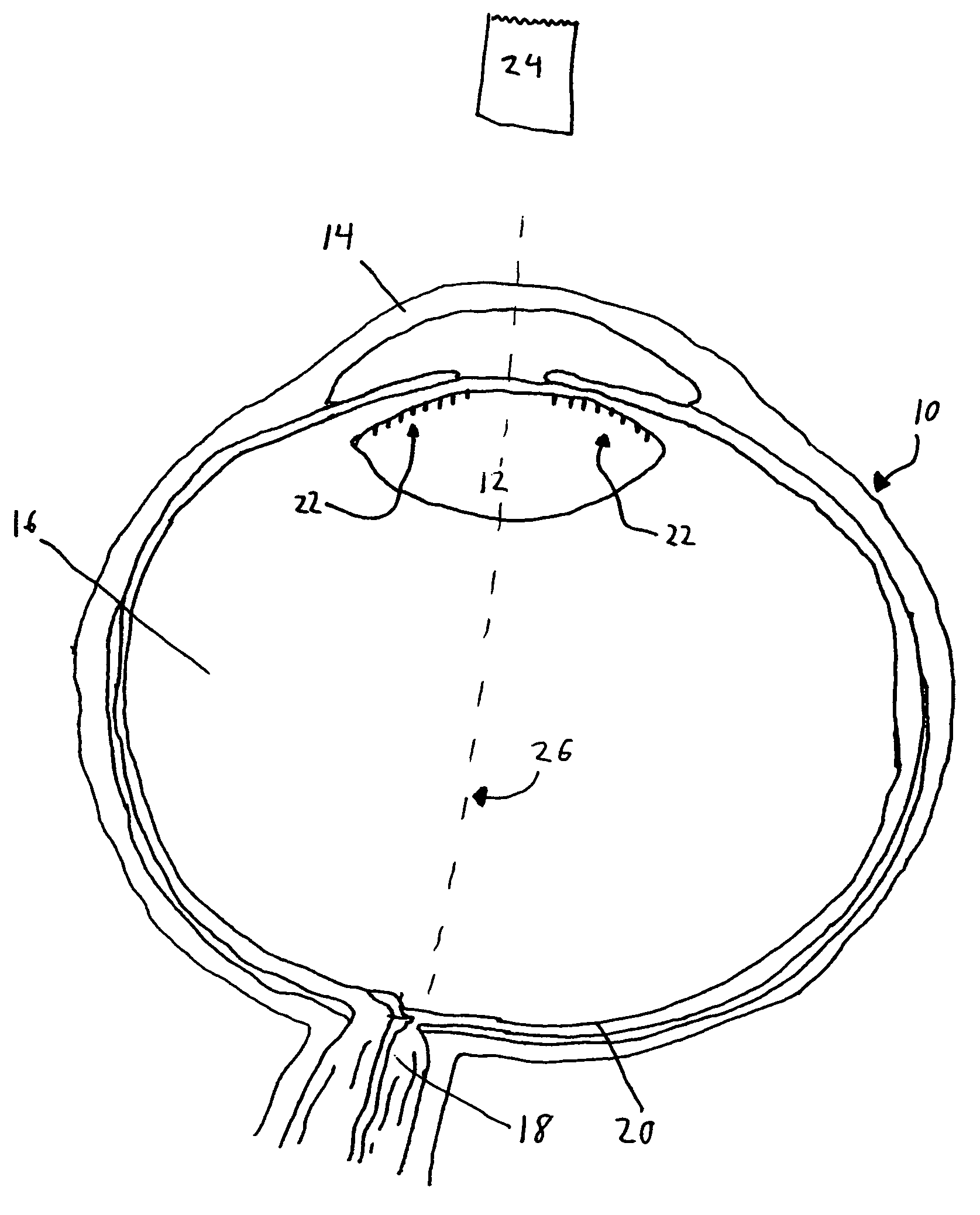
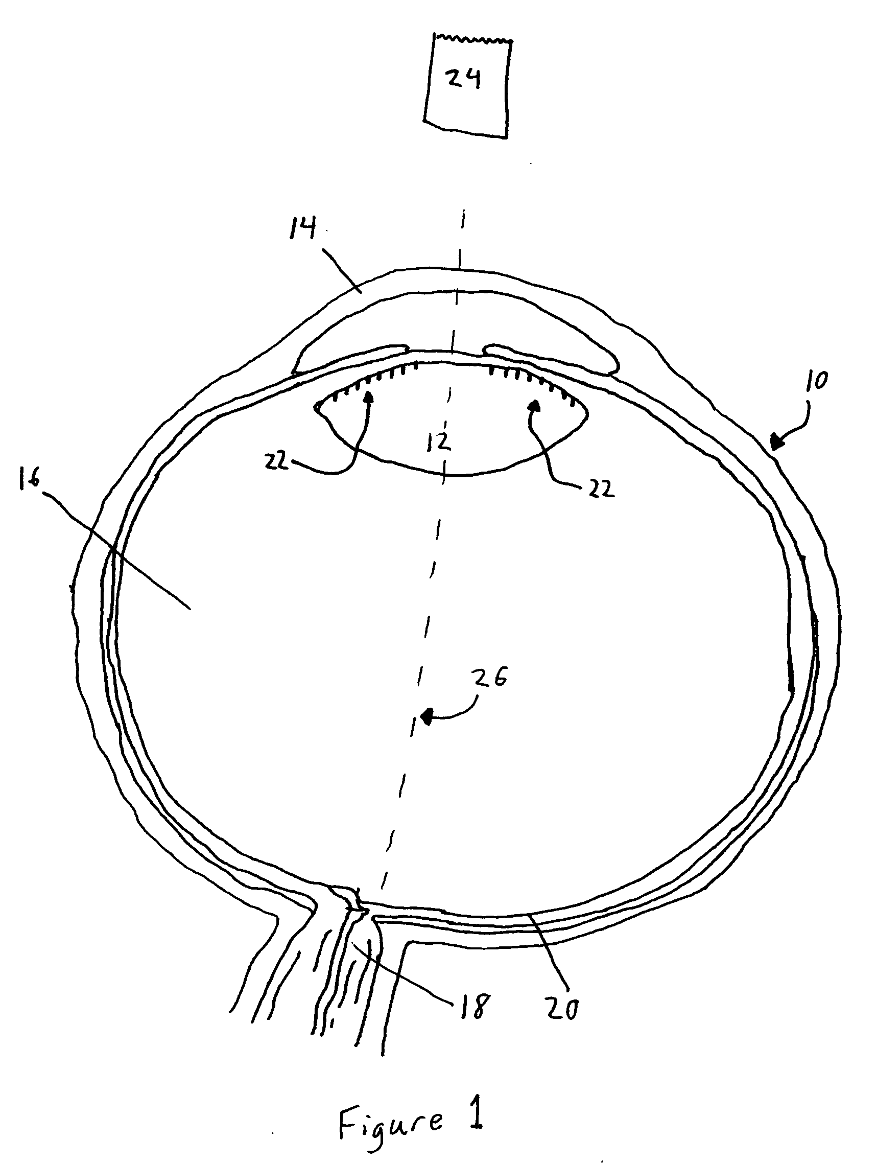
[0025] The optical system of FIG. 1 is an eye 10 in which the lens has been replaced by an IOL 12. The eye 10 generally consists of a cornea 14, the IOL 12, vitreous 16, the optic nerve 18 and a retina 20. IOL 12 is preferably foldable, but may be hard or any other suitable type. Further, the IOL 12 is preferably made from a polymer; however, the IOL 12 can be silicone, acrylic or any other suitable material.
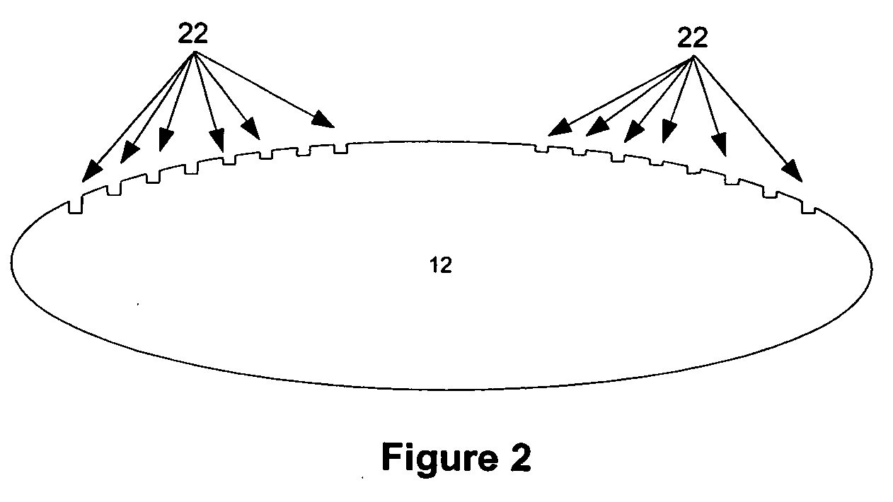
[0026]FIG. 1 shows an optical system which was modified by ablating grooves 22 into a portion of the optical system using a short pulse laser 24. The grooves 22 produce a diffractive effect when light passes through the optical system, improving the optical system's performance. Preferably, the grooves 22 are ablated into an IOL12; however, the grooves can be ablated into a contact lens, eye glasses, the natural lens of the eye 10 or any other suitable portion of the optical system. The grooves 22 are preferably about 1 nanometer to about 50 microns deep and about 1 nanometer t...
PUM
Abstract
A method and apparatus is provided for an intraocular device adapted for adjustment via a laser after implantation into an eye. The intraocular device is inserted into an eye, and one or more optical characteristics of the eye, including the intraocular device, are measured. Then, a groove configuration is determined for the intraocular device, and the configuration is ablated into the intraocular device with a short pulse laser.
Description
CROSS REFERENCE TO RELATED APPLICATIONS [0001] This patent application is a continuation-in-part of U.S. Non-Provisional application Ser. No. 10 / 958,826, filed on Oct. 4, 2004, which is a continuation-in-part of U.S. Non-Provisional application Ser. No. 10 / 272,402, filed on Oct. 17, 2002; and is a continuation-in-part of U.S. Non-Provisional application Ser. No. 10 / 784,169 filed on Feb. 24, 2004, which is a continuation-in-part of U.S. Non-Provisional application Ser. No. 10 / 406,558, filed on Apr. 4, 2003 which claims the benefit of U.S. Provisional Application No. 60 / 449,617, filed on Feb. 26, 2003, and is a continuation-in-part of U.S. Non-Provisional application Ser. No. 10 / 356,730, filed on Feb. 3, 2002, which is a continuation-in-part of U.S. Non-Provisional application Ser. No. 09 / 843,141, filed on Apr. 27, 2001; and is a continuation-in-part of U.S. Non-Provisional application Ser. No. 09 / 986,141, filed on Nov. 7, 2001, the entire contents of each of which are incorporated he...
Claims
Application Information
Patent Timeline
Application Date:The date an application was filed.
Publication Date:The date a patent or application was officially published.
First Publication Date:The earliest publication date of a patent with the same application number.
Issue Date:Publication date of the patent grant document.
PCT Entry Date:The Entry date of PCT National Phase.
Estimated Expiry Date:The statutory expiry date of a patent right according to the Patent Law, and it is the longest term of protection that the patent right can achieve without the termination of the patent right due to other reasons(Term extension factor has been taken into account ).
Invalid Date:Actual expiry date is based on effective date or publication date of legal transaction data of invalid patent.