Time delay definition

a time delay and definition technology, applied in adaptive control, phase difference detection, instruments, etc., can solve the problems of inefficient process control methods of accounting for lags, inability to teach or suggest specific mechanisms for determining the relationship between variables and process delay time, and inability to maximize the performance of a particular process

Inactive Publication Date: 2005-08-18
CONTINUOUS CONTROL SOLUTIONS
View PDF11 Cites 3 Cited by
  • Summary
  • Abstract
  • Description
  • Claims
  • Application Information

AI Technical Summary

Benefits of technology

[0008] A method for controlling a system includes determining the lag in data from a variable signal. The data is arranged in matrices with one column for each variable signal. The columns are shifted to produce a plurality of different shifted matrices, each shifted matrix having a given value for the lag in data for each variable signal. A variable signal estimator processes each shifted matrix to output a variable signal function defining each variable signal in terms of its mathematical dependencies on all of the variable signals. A criterial function processes each variable signal function to provide an optimal lag value for each variable signal. A point calculation algorithm processes each shifted matrix to produce a point for each column. A lag estimator processes each point and optimal lag value to output a lag function defining each lag in terms of its mathematical dependency on all of the variable signals.

Problems solved by technology

Second, it is the difference between the time when the system's variable has started experiencing a change and the time when the change was over.
However, Blevins fails to teach or suggest a specific mechanism for determining the relationship between the variables and the process delay time (see paragraph of Blevins).
However, these prior art process control methods of accounting for lags are often inefficient at maximizing the performance of a particular process and / or inefficient at ensuring adequate process stability.

Method used


Image

  • Time delay definition
  • Time delay definition
  • Time delay definition

Examples


Embodiment Construction

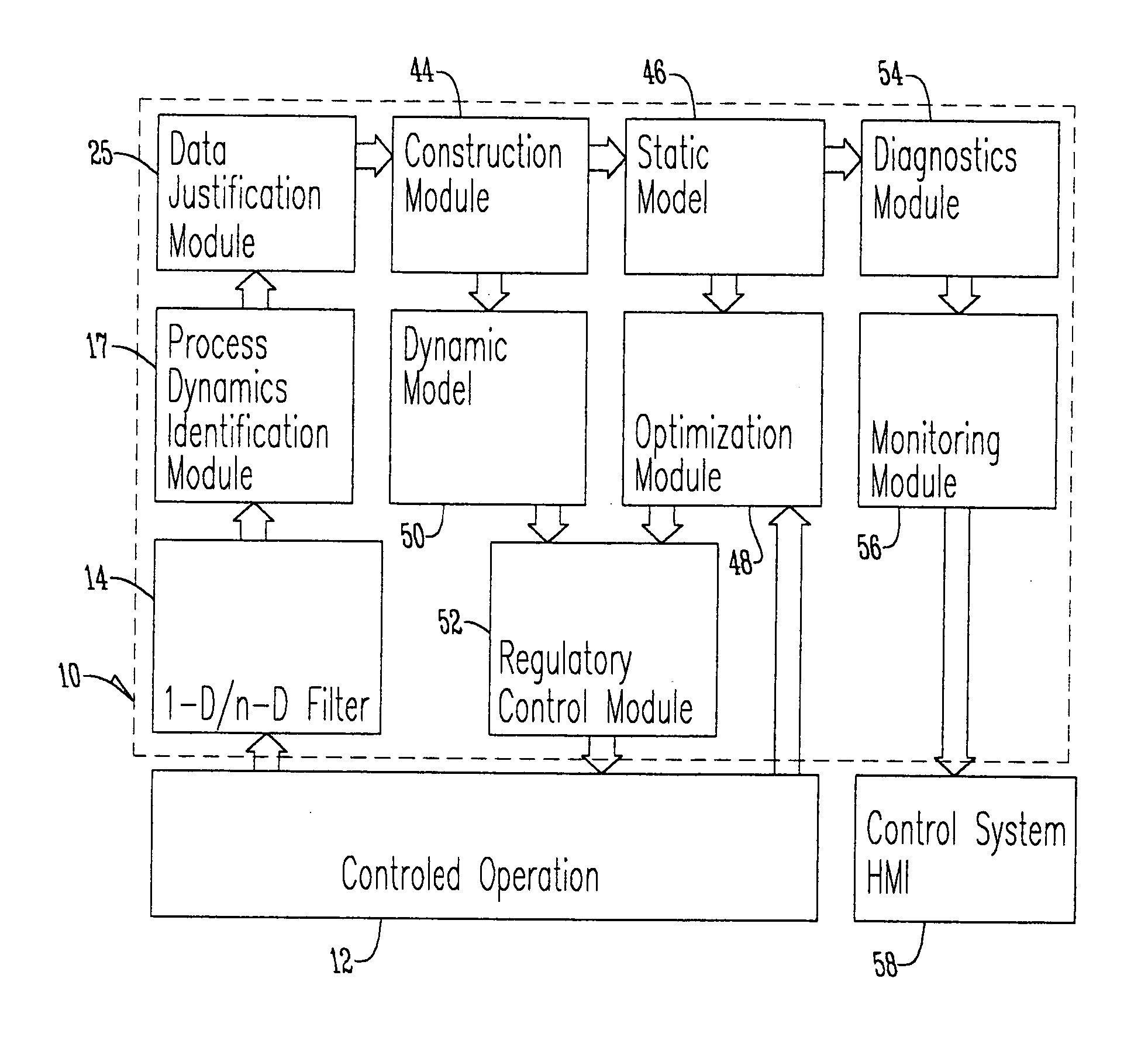
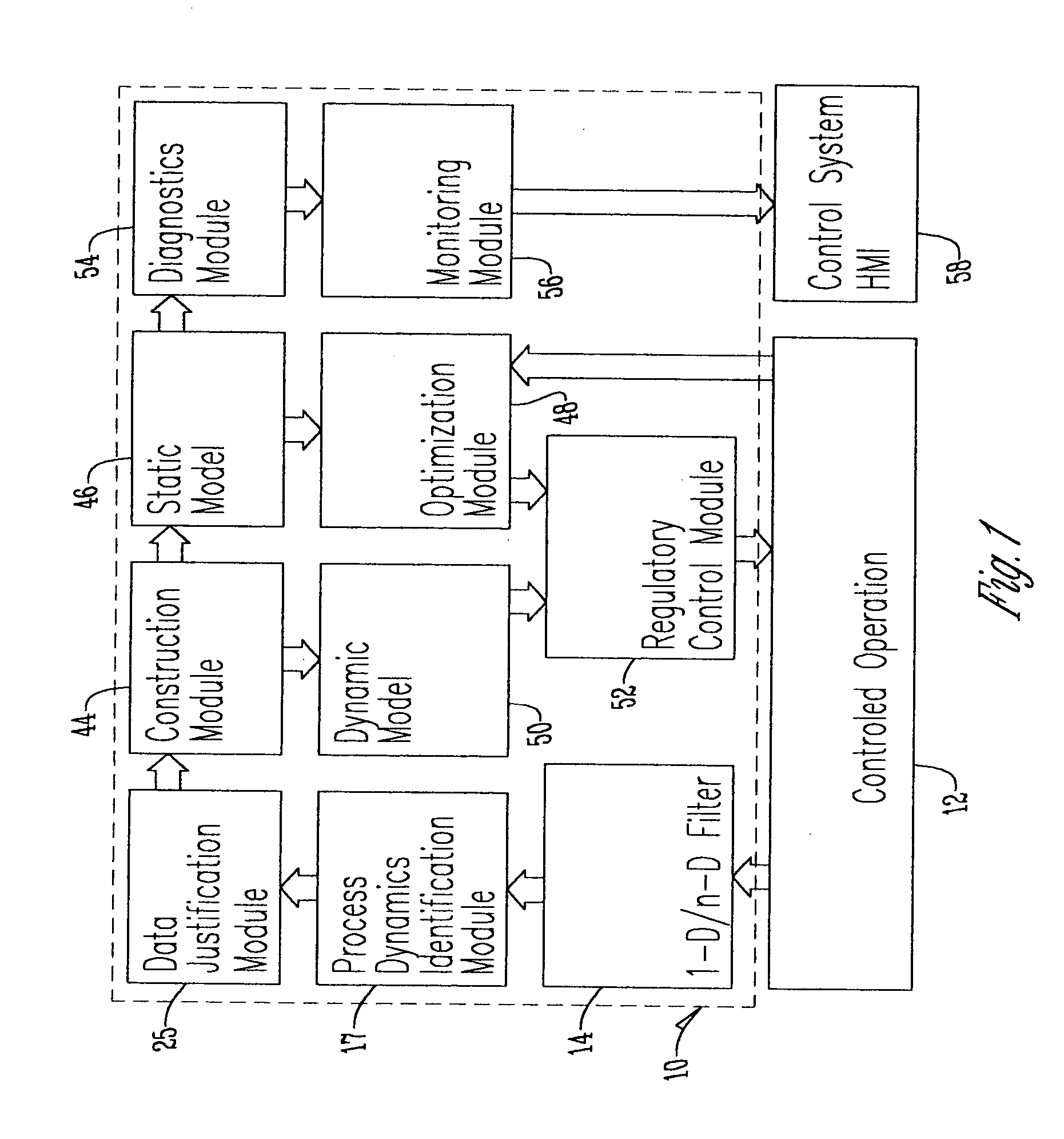
[0020] With reference to FIG. 1, the data mining process control system 10 (DMPC) of the present invention provides continuous process control used for controlling the operation of a controlled operation 12, improving the efficiency of that operation and ensuring regulatory compliance. The DMPC 10 includes multiple interrelated modules that interact with a particular controlled operation 12 to build an accurate model for controlling the operation 12. In general, the DMPC 10 analyzes responses of one continuous variable as a function of one or more continuous independent variables to model the operation 12. Thus, while traditional methods of modeling an operation require the operation to be at steady state conditions, the DMPC 10 converts dynamically collected data into correspondent steady state data subsets.

[0021] The initial input processing by the DMPC 10 consists of several steps. The filter 14 receives measured process variables data (hereinafter “measured data”) sent from the...


PUM


Abstract

A method for controlling a system includes determining the lag in data from a variable signal. The data is arranged in matrices with one column for each variable signal. The columns are shifted to produce a plurality of different shifted matrices, each shifted matrix having a given value for the lag in data for each variable signal. A variable signal estimator processes each shifted matrix to output a variable signal function defining each variable signal in terms of its mathematical dependencies on all of the variable signals. A criterial function processes each variable signal function to provide an optimal lag value for each variable signal. A point calculation algorithm processes each shifted matrix to produce a point for each column. A lag estimator processes each point and optimal lag value to output a lag function defining each lag in terms of its mathematical dependency on all of the variable signals.

Description

BACKGROUND OF THE INVENTION [0001] The present invention relates to the field of process control methods, more particularly to a process control method for controlling a process with lag in data from a variable signal. [0002] Lag in data from a variable's signal, or “τ”, can be defined in three ways. First, it is the difference between the time when a turbo-machinery system's variable has changed and the time when a transmitter has sent the true value of that variable. Second, it is the difference between the time when the system's variable has started experiencing a change and the time when the change was over. Third, it can be a combination of the first two cases. In short, τ can be defined as a lag in the variable's signal (hereinafter “lag”). [0003] Various methods of accounting for these lags are known in the art of process control. For example, U.S. Publication No. U.S. 2003 / 0149493 A1 to Blevins et al. (hereinafter “Blevins”) suggests running a routine to determine if process...

Claims


Application Information

Patent Timeline
Patent Type & Authority Applications(United States)
IPC IPC(8): G05B13/02G05B13/04G05B17/02G05B23/02H03D3/18
CPCG05B13/047
Inventor SHAPIRO, VADIMKHOTS, DMITRIYMARKEVICH, ILYA
Owner CONTINUOUS CONTROL SOLUTIONS
Why Eureka
Try Eureka