Self-propelling cleaner

a cleaner and self-propelling technology, applied in the direction of cleaning equipment, cleaning action control, electric equipment installation, etc., can solve the problems of difficult to determine the full dust state, difficult to accurately detect the amount of dust within the dust chamber, and difficult to determine whether the operation is stopped

Inactive Publication Date: 2005-08-25
FUNAI ELECTRIC CO LTD
View PDF2 Cites 181 Cited by
  • Summary
  • Abstract
  • Description
  • Claims
  • Application Information

AI Technical Summary

Benefits of technology

[0010] Accordingly, one of objects of the invention is to provide a self-propelling cleaner which can surely detect a dust full state within a dust chamber irrespective of kinds of dust and surely notify dust full information to a user.

Problems solved by technology

However, according to the aforesaid conventional dust detection unit, it is not easy to accurately detect an amount of dust within the dust chamber.
However, since an amount of reflection light changes depending on the kind of dust accumulated within the dust chamber and so an amount of light received by the light receiving portion also changes, a dust full state cannot be determined easily.
However, when the operation is stopped, it is difficult to determine whether the operation is stopped due to a failure or due to the termination of the cleaning operation.
Further, in the case of the light alarm, since a small-sized light emitting element such as an LED is used as the light emitting portion, it is difficult for a user to recognize the alarm.
Furthermore, in the case of the sound alarm, such an alarm cannot be used at the time of cleaning an area where a silent state is required to be kept.

Method used


Image

  • Self-propelling cleaner
  • Self-propelling cleaner
  • Self-propelling cleaner

Examples


first embodiment

[0023] A self-propelling cleaner according to the invention will be explained with reference to drawings. In the embodiment, the explanation will be made as to a self-propelling cleaner of a strike-up type which strikes dust up by a brush within a nozzle and accommodates the dust thus struck-up within a dust chamber.

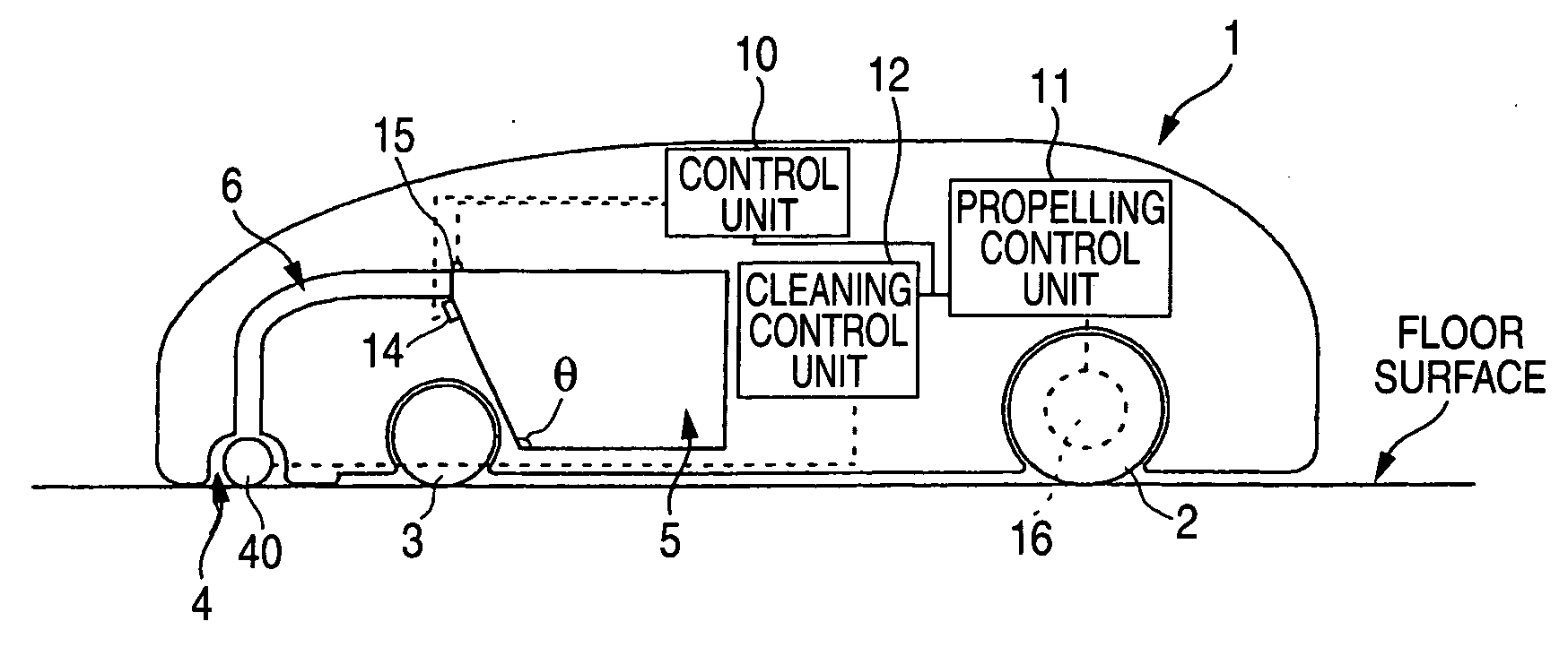
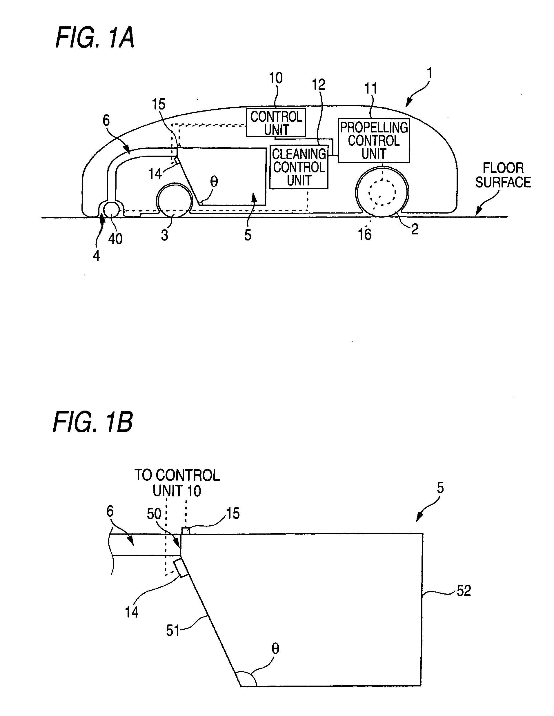
[0024]FIG. 1A is a block diagram showing the schematic configuration of the self-propelling cleaner according to this embodiment, and FIG. 1B is an enlarged sectional diagram showing a dust chamber 5.

[0025] The self-propelling cleaner is configured by a propelling control unit and a propelling unit for propelling a main body 1 along a route within a cleaning region set in advance, and a cleaning unit for removing dust on the floor surface within the cleaning region and accommodating the dust therein.

[0026] Driving wheels 2 and driving motors 16 coupled to the driving wheels 2 to rote the driving wheels 2 are provided at the left and right portions of the lower portion ...

second embodiment

[0041] Next, the self-propelling cleaner will be explained with reference to FIGS. 5A and 5B. In this embodiment, the explanation will be made as to a self-propelling cleaner of a vacuum type which is provided with an evacuation fan at the dust chamber.

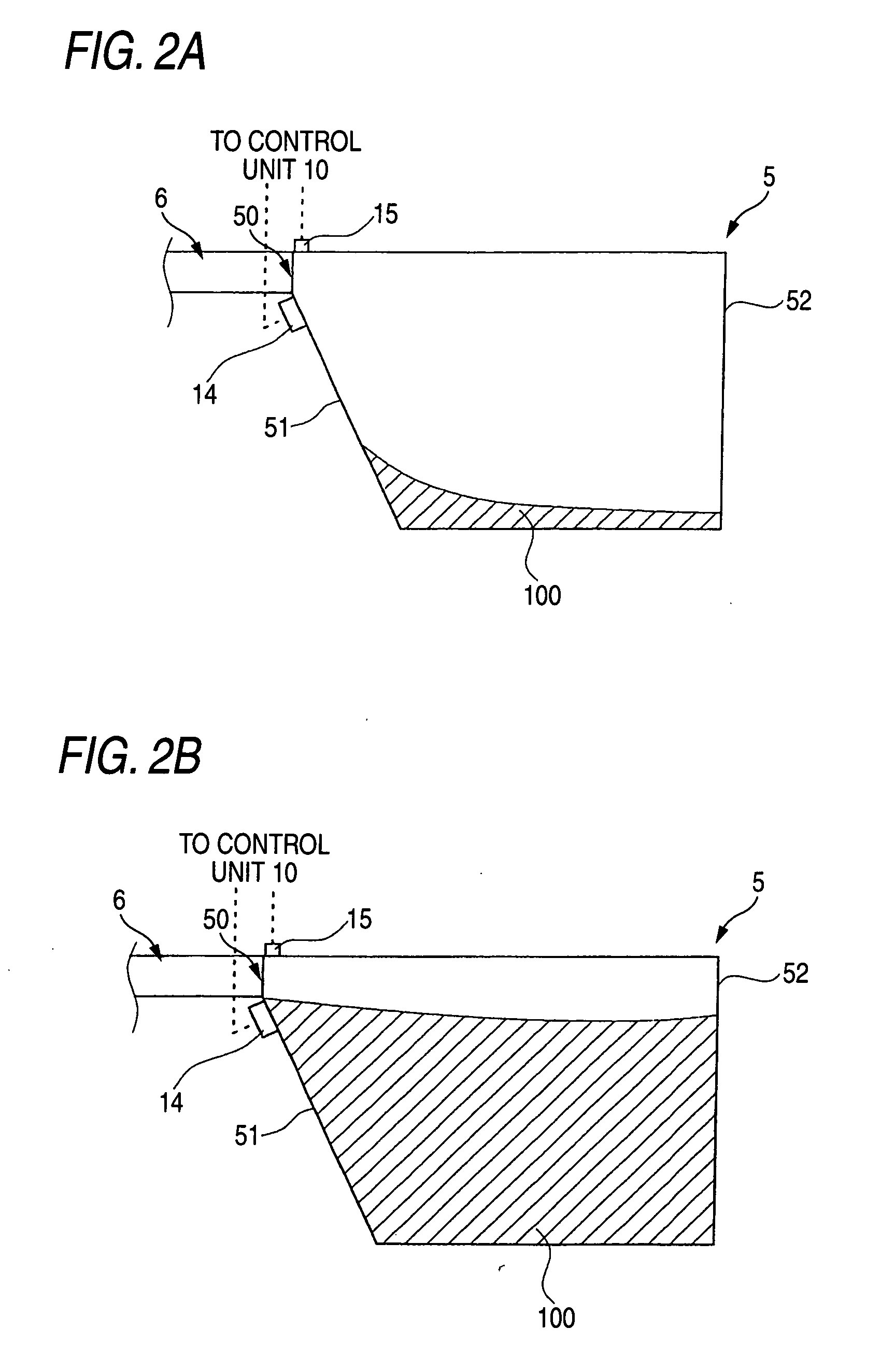
[0042]FIGS. 5A and 5B are side views showing the schematic configurations near the dust chamber of the self-propelling cleaner according to this embodiment, wherein FIG. 5A shows a state where an amount of dust accumulated within a dust chamber 5 is small, and FIG. 5B shows a state where the dust chamber 5 is filled with dust.

[0043] The self-propelling cleaner shown in FIGS. 5A and 5B includes an evacuation fan 21 on a side wall 52 opposing to a side wall 51 having a coupling hole 50 coupled to a dust transporting pipe 6 within the dust chamber 5. The evacuation fan 21 is driven by a fanmotor 22. The fan motor 22 is controlled in its operation by a cleaning control unit 12. The remaining configuration of this embodiment is same as t...

third embodiment

[0045] Next, the self-propelling cleaner will be explained with reference to FIGS. 6A-6C.

[0046]FIGS. 6A-6C are side views showing the schematic configurations near the dust chamber of the self-propelling cleaner according to this embodiment, wherein FIG. 6A shows a state where an amount of dust accumulated within a dust chamber 5 is small, FIG. 6B shows a state where an amount of dust accumulated within the dust chamber 5 is close to full, and FIG. 6C shows a state where the dust chamber 5 is filled with dust.

[0047] The self-propelling cleaner shown in FIGS. 6A-6C is configured in a manner that photo detectors 14a, 14b are attached to different vertical positions on the side wall 51 of the dust chamber 5, and photo diodes 15a, 15b for irradiating lights toward the photo detectors 14a, 14b are provided on the upper surface of the dust chamber 5, respectively. The remaining configuration of this embodiment is same as the self-propelling cleaner shown in FIG. 1. The photo detector 14...


PUM


Abstract

A side wall 51 provided with a coupling hole 50 coupled to the dust transporting pipe 6 of a dust chamber 5 is configured in a sloped shape so as to have a predetermined angle θ with respect to the bottom surface of the dust chamber. A photo detector 14 having a light receiving surface along the surface 51 is disposed near the coupling hole 50 of the side wall 51. A photo diode 15 for irradiating light toward the photo detector 14 is disposed on the upper surface of the dust chamber 5. When dust is filled within the dust chamber 5, since dust is accumulated on the photo detector 14, the photo detector 14 does not outputs a light detection signal.

Description

BACKGROUND OF THE INVENTION [0001] 1. Field of the Invention [0002] The present invention relates to a self-propelling cleaner which performs cleaning while automatically propelling in a cleaning range. [0003] 2. Description of the Related Art [0004] A self-propelling cleaner includes a propelling unit for propelling a main body thereof and a cleaning unit for performing cleaning and performs cleaning while automatically propelling in a cleaning range set in advance. [0005]FIG. 8 is a diagram showing the schematic configuration of a conventional self-propelling cleaner. [0006] As shown in FIG. 8, the conventional self-propelling cleaner is provided in a main body 1 with driving wheels 2, driven wheels 8, and further provided with a nozzle 4 having a brush 40 which contacts with the floor surface and rolls up dust on the floor surface, a dust chamber 5 for accommodating dust thus rolled up by the nozzle 4, and a dust transporting pipe 6 for introducing dust from the nozzle 4 to the d...

Claims


Application Information

Patent Timeline
Patent Type & Authority Applications(United States)
IPC IPC(8): A47L9/00A47L9/19A47L9/28
CPCA47L9/009A47L9/19A47L9/2805A47L2201/06A47L9/2857A47L9/2889A47L9/2852
Inventor UEHIGASHI, NAOYA
Owner FUNAI ELECTRIC CO LTD
Why Eureka
Try Eureka