Inertia sensor unit

a sensor unit and inertia technology, applied in the direction of speed/acceleration/shock measurement devices, instruments, navigation instruments, etc., can solve the problems that the output signals of the angular sensor and the acceleration sensor cannot be accurately corrected with the temperature detected, and the accuracy of each output signal cannot be achieved. , to achieve the effect of accurate judgment of failures and improved reliability of inertia sensor units

Active Publication Date: 2005-08-25
HONDA MOTOR CO LTD
View PDF8 Cites 12 Cited by
  • Summary
  • Abstract
  • Description
  • Claims
  • Application Information

AI Technical Summary

Benefits of technology

[0019] In the inertia sensor unit equipped with the above constitution, the failure judging means performs judgement by the temperature of the signal processor detected by the first temperature detecting means and the temperature of the detecting element detected directly or indirectly by the second temperature detecting means, whereby the inertia sensor unit can accurately judge a failure of the inertia sensor. As a result, it is possible to improve the reliability of the inertia sensor unit.

Problems solved by technology

However, the above traditional sensors have a problem that the signals output from the angular sensor and the acceleration sensor cannot be accurately corrected with the temperature detected by the temperature sensor, because the temperature detected by the temperature sensor may differ depending on the number and arrangement of the temperature sensor, i.e. in the case in which the temperature is elevated by the heat generated by the ASIC and the microcomputer itself which processes the output signal of a sensor, and the case in which the temperature is elevated by the heat from an outer environment, although the accuracy of the output from the sensor is improved compared with the case of doing nothing.
In particular, in an inertia sensor in which a detecting element and a signal-processor for processing the signals output from the detecting element are constituted as individual elements respectively, there was a problem that each output signals could not be corrected accurately with the exact temperature depending on the arrangement place of the temperature sensor, because a difference in temperature occurred between the detecting element and the signal-processor.

Method used


Image

  • Inertia sensor unit
  • Inertia sensor unit
  • Inertia sensor unit

Examples


Embodiment Construction

[0026] Hereafter, with reference to drawings, one example of the present invention will be explained.

Overall Constitution

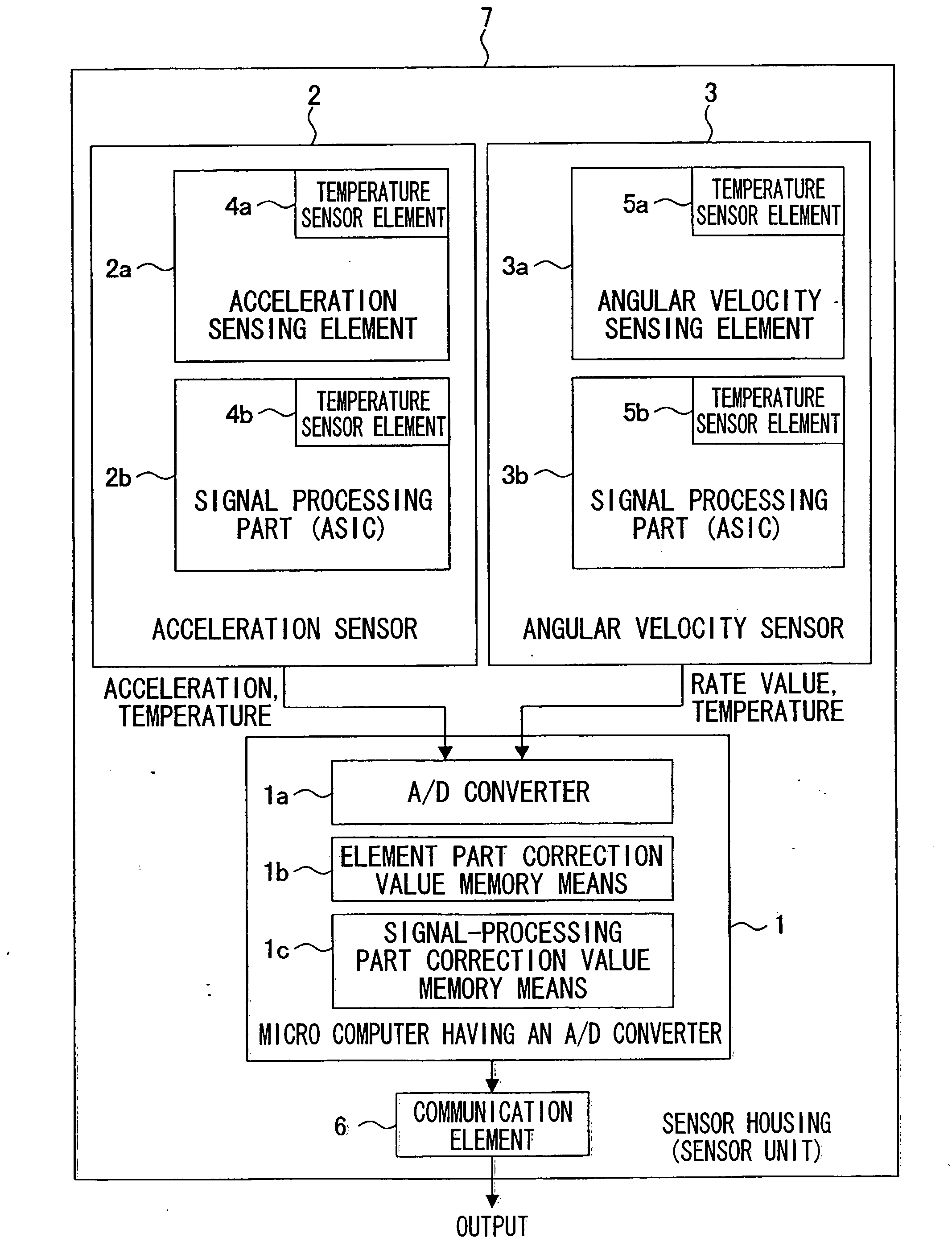
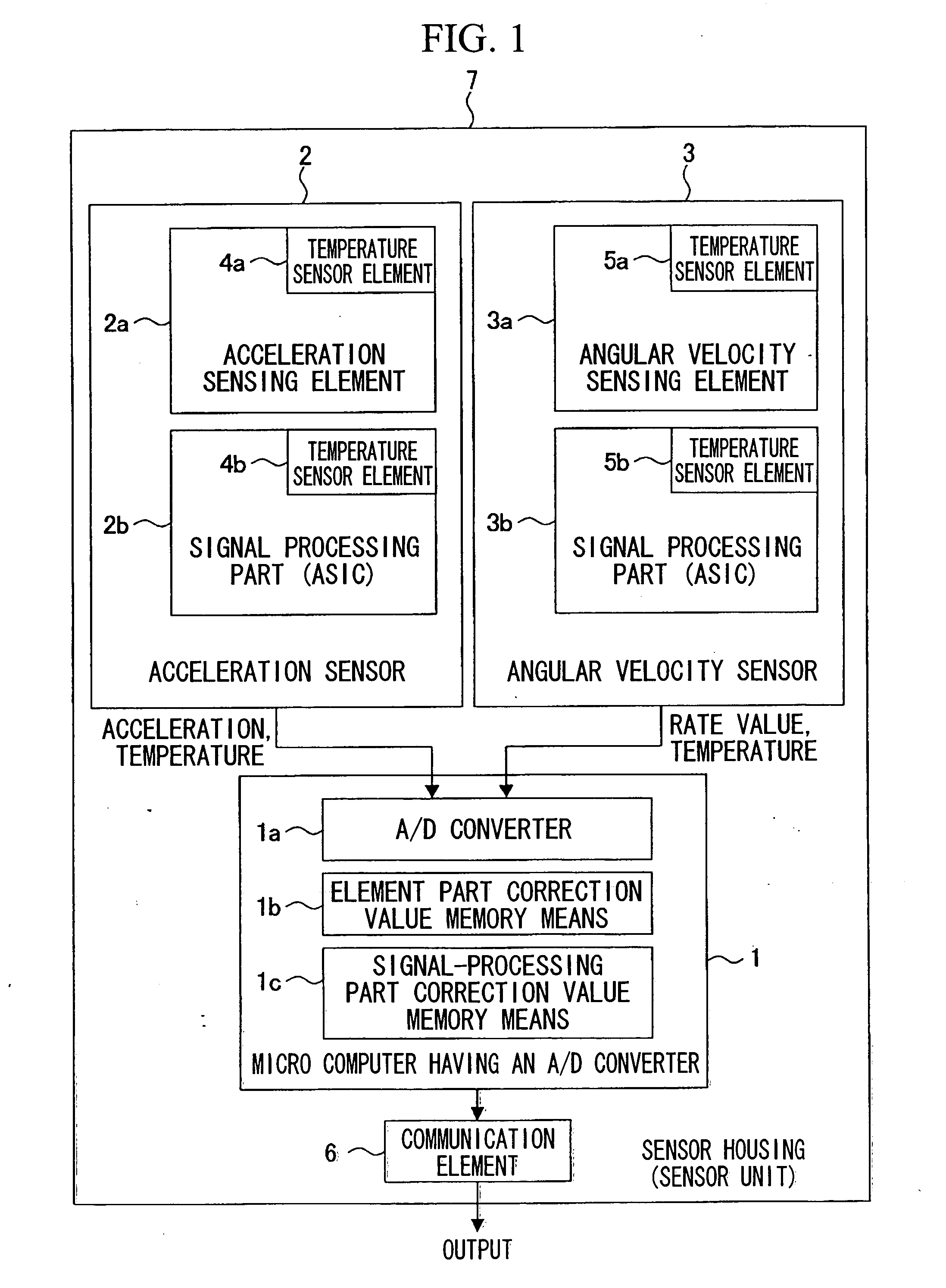
[0027]FIG. 1 is a block diagram showing the constitution of the inertia sensor unit of one example of the present invention. It should be noted that the inertia sensor unit of this example of the present invention is especially useful as an inertia sensor which is installed in vehicles such as an automobile and the like, and hence it will be explained for a case-in which an inertia sensor unit is installed in an automobile.

[0028] In FIG. 1, the microcomputer 1 having an A / D converter is a control part which constitutes the center of the inertia sensor unit of the example of the present invention. The microcomputer 1 having an A / D converter is, for example, equipped with a 10-bit A / D converter 1a, in order to take analog signals which are output from various sensors arranged at appropriate locations of the automobile output into the microcomputer 1 having an A / ...


PUM


Abstract

An inertia sensor unit having a detecting element, a signal processor being constituted as an element separate from the detecting element, for at least amplifying signals output from the detecting element, and an inertia sensor mounted to a detection object for detecting acceleration or angular velocity of the detection object as an inertial force of the detection object to output electrical signals changing according to the inertial force, includes: a first temperature detecting means for detecting the temperature of the signal processor, a second temperature detecting means for detecting the temperature of the detecting element directly or indirectly, and a correcting means for correcting the signals output from the inertia sensor based on the result detected by the first temperature detecting means and the second temperature detecting means.

Description

BACKGROUND OF THE INVENTION [0001] 1. Field of the Invention [0002] This invention relates to an inertia sensor unit mounted on vehicles and the like. [0003] Priority is claimed on Japanese Patent Application No. 2003-359097, filed Oct. 20, 2003, the content of which is incorporated herein by reference. [0004] 2. Description of Related Art [0005] Conventionally, in observing a position or an orientation of vehicles, a flying object and the like, measurement of angular velocity and acceleration is performed and, for this reason, inertia sensors, such as an angular velocity sensor and an acceleration sensor, are used. It is general to convert the analog electricity signals output from inertia sensors, such as an angular velocity sensor and an acceleration sensor into digital signals corresponding to resolutions as occasion demands, respectively, through an A / D converter. [0006] Moreover, it is also common to correct signals output from an angular velocity sensor and an acceleration se...

Claims


Application Information

Patent Timeline
Patent Type & Authority Applications(United States)
IPC IPC(8): G01C21/16G01P15/00G01P21/00G01P21/02
CPCG01P21/00G01C21/16G01C21/183
Inventor SAITO, KAZUTAKANAKAMUTA, AKIRAUENO, ICHIROSATO, FUMIKIHIYAMA, SATOSHI
Owner HONDA MOTOR CO LTD
Why Eureka
Try Eureka