Apparatus and method for the control of trailing wake flows

a technology of wake flow and apparatus, applied in the direction of airflow influencers, drag reduction, transportation and packaging, etc., can solve the problem of insufficient danger in causing airplane crash

Active Publication Date: 2005-08-25
THE BOEING CO
View PDF29 Cites 65 Cited by
  • Summary
  • Abstract
  • Description
  • Claims
  • Application Information

AI Technical Summary

Problems solved by technology

The size and intensity of wake vortices is determined by the size and weight of the aircraft, and pose particularly dangerous conditions in the wake of wide body airplanes.
In worst case scenarios, these can be sufficiently dangerous in causing airplane crashes.

Method used


Image

  • Apparatus and method for the control of trailing wake flows
  • Apparatus and method for the control of trailing wake flows
  • Apparatus and method for the control of trailing wake flows

Examples


Embodiment Construction

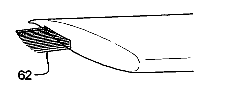
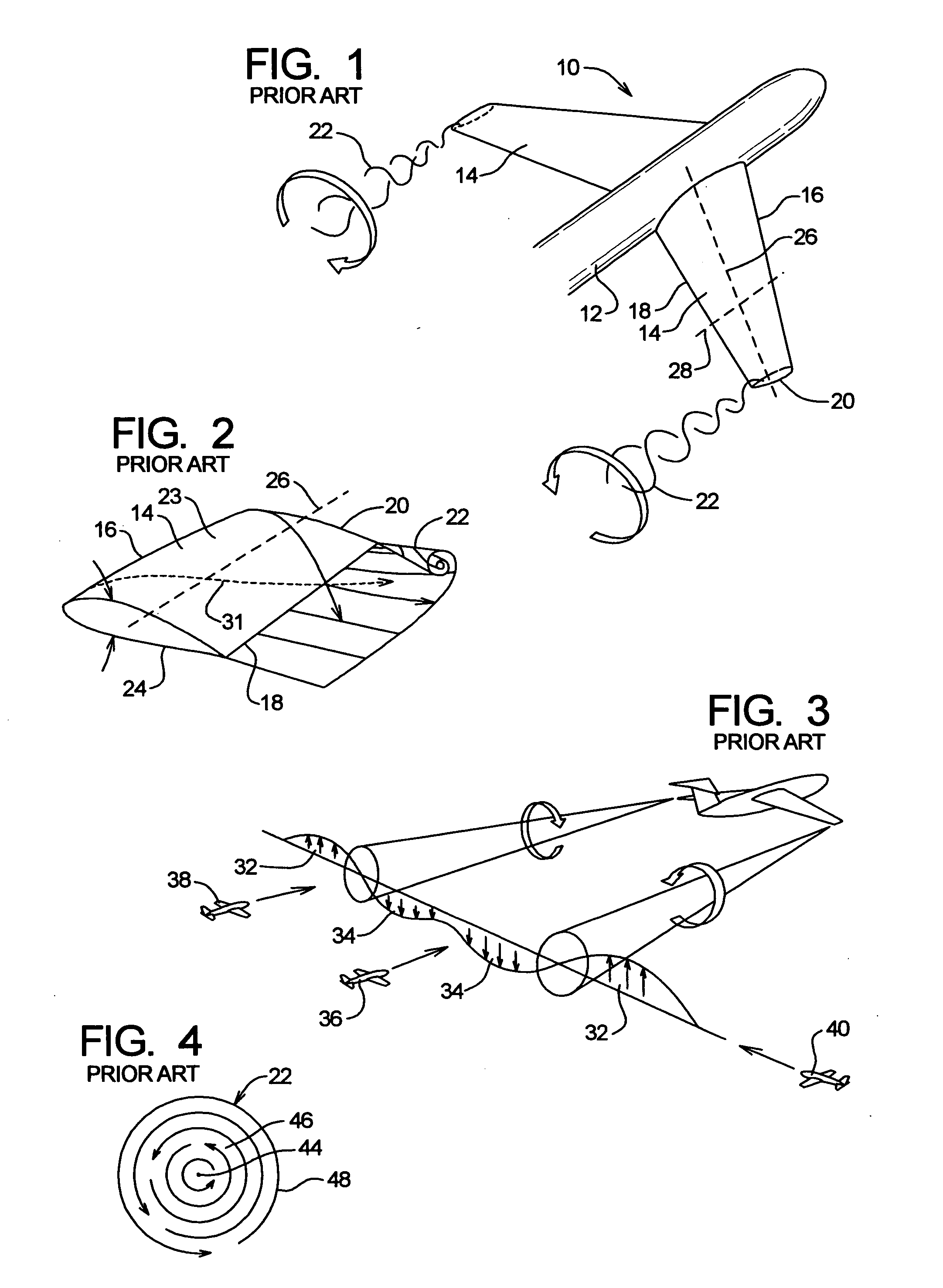
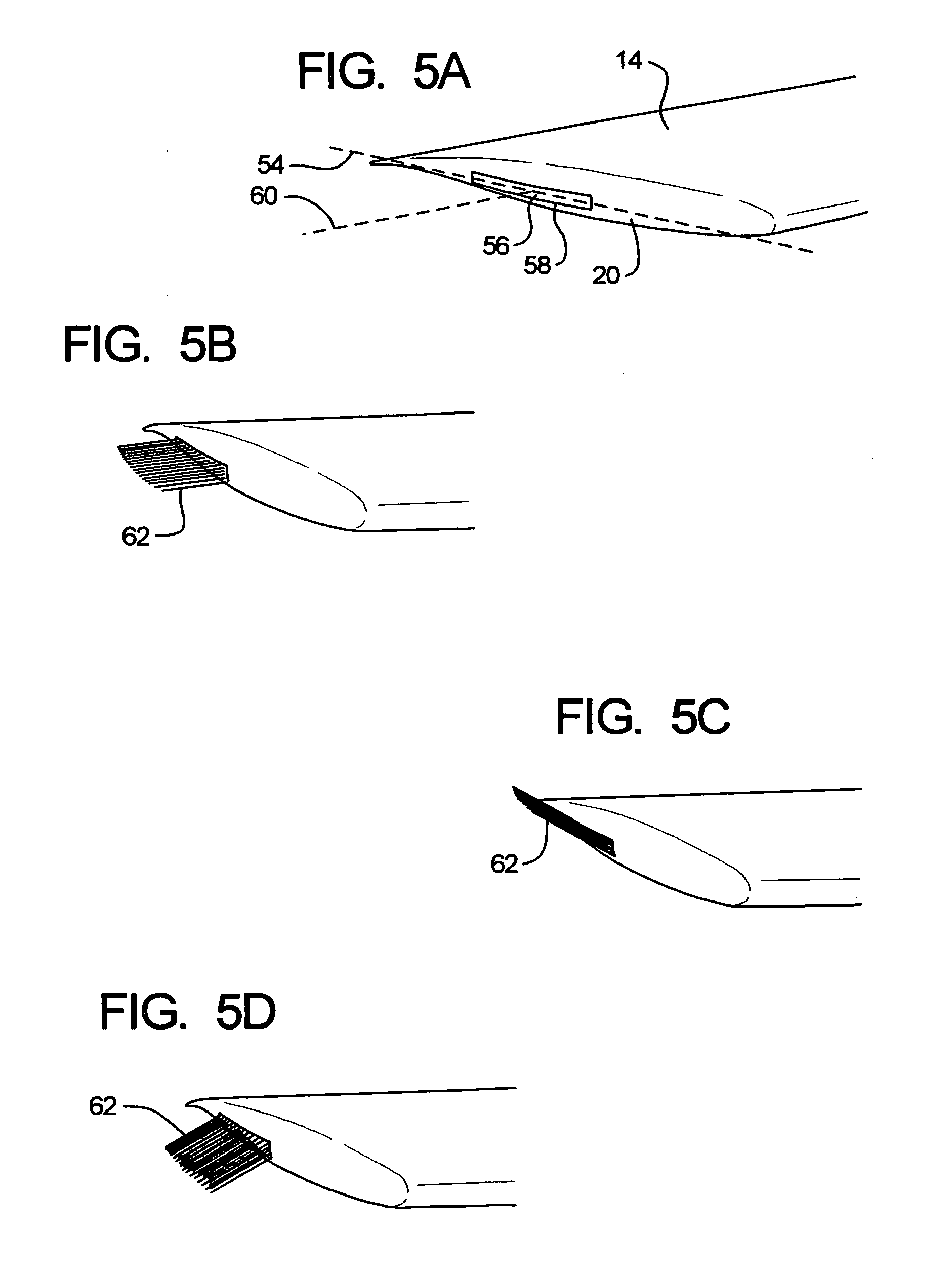
[0046] The embodiments of the present invention comprise an airfoil vortex dissipating system and a method relating to the same. The airfoil in which the system is incorporated has a leading edge, a trailing edge, an outer edge portion, an upper aerodynamic surface, a lower aerodynamic surface, a spanwise axis, a forward to rear chord axis, and an alignment reference plane coincident with the spanwise axis and the chord axis. The airfoil is characterized in that when the airfoil is functioning to create aerodynamic lift, a vortex is created at the outer end portion of the airfoil. The airfoil has a vortex core axis, a main circumferential flow region and an outer perimeter flow region.

[0047] The vortex dissipating apparatus comprises a nozzle section which is at or proximate to the outer end portion of the airfoil, and has a nozzle discharge portion which in this embodiment is at an alignment location extending generally in a forward to rearward direction at, or proximate to, the o...


PUM


Abstract

A system and method for dissipating vortices that form at the wingtips on aircraft and from other airfoils. A jet air stream is discharged in a location at or proximate to the outer end portion of the airfoil into the vortex flow, and the jet air stream is moved cyclically back and forth. The cyclic movement can be at lower or higher frequencies to alleviate at least in part intensity of the vortex or accelerate instability of the vortex which leads to vortex dissipation.

Description

BACKGROUND OF THE INVENTION [0001] a) Field of the Invention [0002] The present invention relates to alleviating the problem of vortices that form at the outer tips of aerodynamic surfaces, and more particularly the problem of such vortices which are developed by an airplane, especially a rather large airplane, traveling on a flight path, where the vortices can have adverse effects on an airplane which is following (or crossing) that same flight path. [0003] b) Background Art [0004] Current airport capacity is largely controlled by the hours of operation, which are largely confined to daylight hours to prevent noise pollution in the airport environs, and the frequency with which planes can be brought in and out of the airport. A pacing item in landing and takeoff frequency is the time necessary for the dissipation of wake vortices produced by planes in motion. The size and intensity of wake vortices is determined by the size and weight of the aircraft, and pose particularly dangerou...

Claims


Application Information

Patent Timeline
Patent Type & Authority Applications(United States)
IPC IPC(8): B64C23/06
CPCY02T50/164B64C23/065B64C23/076Y02T50/10
Inventor SHMILOVICH, ARVINYADLIN, YORAMCLARK, ROGERLEOPOLD, DONALD
Owner THE BOEING CO
Why Eureka
Try Eureka