Light beam scanning device, image forming apparatus, and light beam scanning method

a scanning device and light beam technology, applied in the direction of instruments, electrographic processes, optical elements, etc., can solve the problems of preventing the correction of affecting the quality of images produced, and different image magnification of mass-produced products, so as to prevent unnecessary design difficulties, and correct magnification errors with accuracy

Inactive Publication Date: 2005-08-25
RICOH KK
View PDF9 Cites 10 Cited by
  • Summary
  • Abstract
  • Description
  • Claims
  • Application Information

AI Technical Summary

Benefits of technology

[0033] Thus, according to one aspect of the present invention, it is possible to correct magnification error with accuracy by causing the condition of the amount of light at the time of detecting a light beam to be constant, while it is also possible to prevent unnecessary difficulties in design from being caused.
[0034] That is, the condition of the amount of light at a measurement part can be constant, while it is possible to prevent unnecessary difficulties in design from being caused without affecting control of the light beam in an image area.

Problems solved by technology

However, with respect to the conventional image forming apparatus, there is a problem in that each mass-produced product has different image magnification because of variations in the characteristics of the lens of its light beam scanning device.
Further, in image forming apparatuses employing multiple laser beams and corresponding lenses to form a multicolor image, color misregistration occurs because of their respective magnification errors, so that a high-quality image may not be produced.
This change of the output timing of the light beam detection signal causes the measured time difference to change, thus causing a problem in that magnification error is prevented from being corrected with accuracy.
Considering the case of performing shading correction as performed in Document 4, for instance, an attempt to make constant the light beam intensity in the area other than the image area, where an image is formed, may make it difficult to return the amount of light to a desired value in the image area.
However, providing a large number of light amount correction points as described above increases a control circuit in scale.
As a result, the amount of light varies significantly at points where the level of the correction signal switches as illustrated in FIG. 3B, thus resulting in degraded image quality.
However, in the case of changing the amount of light greatly, the change cannot be followed, thus causing a problem in that it takes time before the amount of light reaches an actual set value.
Therefore, it may be difficult for the technique of Document 3 to return the amount of light immediately to a desired value at a position where the area other than the image area switches to the image area.

Method used


Image

  • Light beam scanning device, image forming apparatus, and light beam scanning method
  • Light beam scanning device, image forming apparatus, and light beam scanning method
  • Light beam scanning device, image forming apparatus, and light beam scanning method

Examples


first embodiment

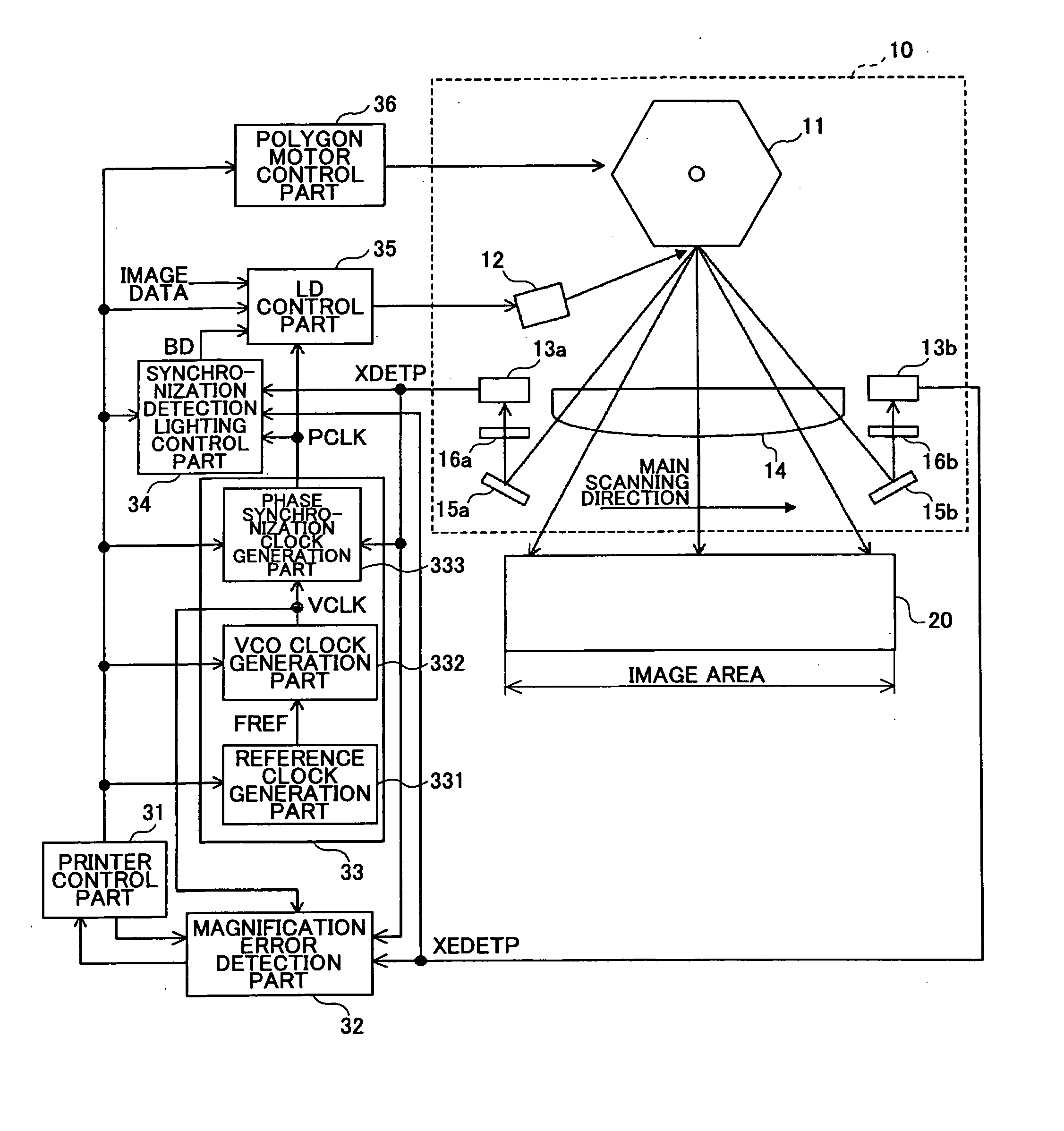
[0057]FIG. 4 is a schematic diagram illustrating a configuration of a light beam scanning device 10, a photosensitive body 20, and their periphery in an image forming apparatus according to a first embodiment of the present invention.

[0058] In the light beam scanning device 10, the light beam of an LD, controlled based on image data to light up, is converted into a parallel beam by a collimator lens (not graphically illustrated), and goes through a cylinder lens (not graphically illustrated) to be deflected by a polygon mirror 11 rotated by a polygon motor 1. Then, the light beam goes through an fθ lens 14 and a barrel toroidal lens (BTL) 2 to be reflected by a deflecting mirror 3 so as to scan the surface of the photosensitive body 20. The BTL 2 performs focusing in the sub scanning direction. That is, the BTL 2 has the function of condensing, and performs positional correction in the sub scanning direction, such as face tangle error correction.

[0059] A charger 4, a development u...

second embodiment

[0078] Next, a description is given of an image forming apparatus according to a second embodiment of the present invention. The image forming apparatus of this embodiment is equal to that of the first embodiment in the general configuration of each of the parts of the image forming apparatus, such as the light beam scanning device 10 and the image formation control part, and has the same control flow as that of FIG. 9 of the first embodiment. In the image forming apparatus of the second embodiment, the point-to-point measurement is performed with a maximum amount of light.

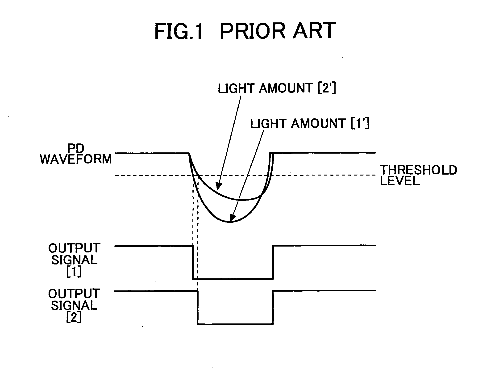
[0079]FIG. 1 illustrates a change in the timing of the output signal (XDETP / XEDETP) due to a change in the amount of light. According to the second embodiment, the amount of light at the time of performing the point-to-point measurement is set to a maximum value (a maximum amount of light possible as a system). As a result, a change in timing with respect to a change in the amount of light can be further controll...

third embodiment

[0081] Next, a description is given of an image forming apparatus according to a third embodiment of the present invention. The image forming apparatus of this embodiment is equal to that of the first embodiment in the general configuration of each of the parts of the image forming apparatus, such as the light beam scanning device 10 and the image formation control part, and has the same control flow as that of FIG. 9 of the first embodiment. In the image forming apparatus of the third embodiment, the amount of light at the time of performing the point-to-point measurement is set to the medium value of a light amount variation range within which the amount of light is variable.

[0082]FIG. 10 illustrates the transition of the amount of light from a time at which the setting of the amount of light is returned to that for image formation after completion of the point-to-point measurement to a time at which the amount of light reaches the set value. In the case of a system that performs...


PUM


Abstract

A light beam scanning device is disclosed that includes a light emission source to emit a light beam, a deflection part to deflect the emitted light beam in the main scanning direction, first and second light beam detection parts to detect the deflected light beam at first and second positions, respectively, outside an image area on the opposite sides thereof in the main scanning direction, a time difference measurement part to measure the time difference between the light beam detections by the first and second light beam detection parts, and a control part to perform control so as to correct image magnification in the main scanning direction in the image area from the measured time difference. The control part performs control so that the condition of the amount of light at the time of detecting the light beam by the first and second light beam detection parts is constant.

Description

BACKGROUND OF THE INVENTION [0001] 1. Field of the Invention [0002] The present invention relates to a light beam scanning device that performs scanning with a light beam from a light source while detecting the light beam, an image forming apparatus, and a light beam scanning method. [0003] 2. Description of the Related Art [0004] In general, an image forming apparatus employing a light beam scanning device modulates a light beam by image data, deflects the light beam at constant angular velocity in the main scanning direction by rotating a polygon mirror, and corrects the deflection of constant angular velocity to deflection of constant linear velocity, thereby scanning the surface of a photosensitive body. [0005] However, with respect to the conventional image forming apparatus, there is a problem in that each mass-produced product has different image magnification because of variations in the characteristics of the lens of its light beam scanning device. In particular, in the cas...

Claims


Application Information

Patent Timeline
Patent Type & Authority Applications(United States)
IPC IPC(8): G02B26/10B41J2/44G02B26/12G03G15/04G03G15/043G03G21/00H04N1/036H04N1/113
CPCG02B26/127
Inventor MAEDA, KATSUHIKO
Owner RICOH KK
Why Eureka
Try Eureka