Standard reference for metrology and calibration method of electron-beam metrology system using the same

a metrology system and electron beam technology, applied in the field of electron beam metrology, can solve the problems of difficult development, limit the accuracy of diffraction angle measurement of grating using laser beam for calibrating purposes, and the exposure device whose laser beam source is altered to a shorter wavelength involves many problems, and achieves the effect of high accuracy, unprecedented size calibration, and easy differentiation

Inactive Publication Date: 2005-08-25
HITACHI HIGH-TECH CORP
View PDF2 Cites 33 Cited by
  • Summary
  • Abstract
  • Description
  • Claims
  • Application Information

AI Technical Summary

Benefits of technology

This patent describes a way to improve the precision and accuracy of measurements taken on small electronic components during manufacturing processes. It involves using special techniques like electron-beam delineation and precise pattern formation to create standards for comparison when making these measurements. These standards help ensure consistent results across multiple machines and even different locations within one machine. Overall, this approach allows for more reliable and efficient quality control throughout the production process.

Problems solved by technology

This patent describes a new method for making standards for measurement in electron-beam metrology. Current methods involve creating a pattern on a semiconductor surface with a special tool called a laser interferometer. However, this can be difficult because it requires very precise measurements from a laser that's hard to control. So there was a technical problem: how could we make better standards for electronic metrology without relying on such a delicate process?

Method used


Image

  • Standard reference for metrology and calibration method of electron-beam metrology system using the same
  • Standard reference for metrology and calibration method of electron-beam metrology system using the same
  • Standard reference for metrology and calibration method of electron-beam metrology system using the same

Examples


Embodiment Construction

[0038] Preferred embodiments of the present invention will be described in detail below with reference to accompanying drawings.

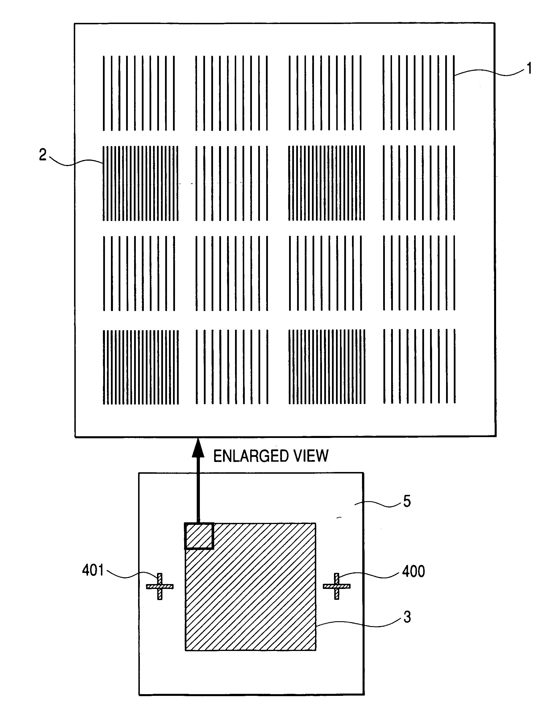
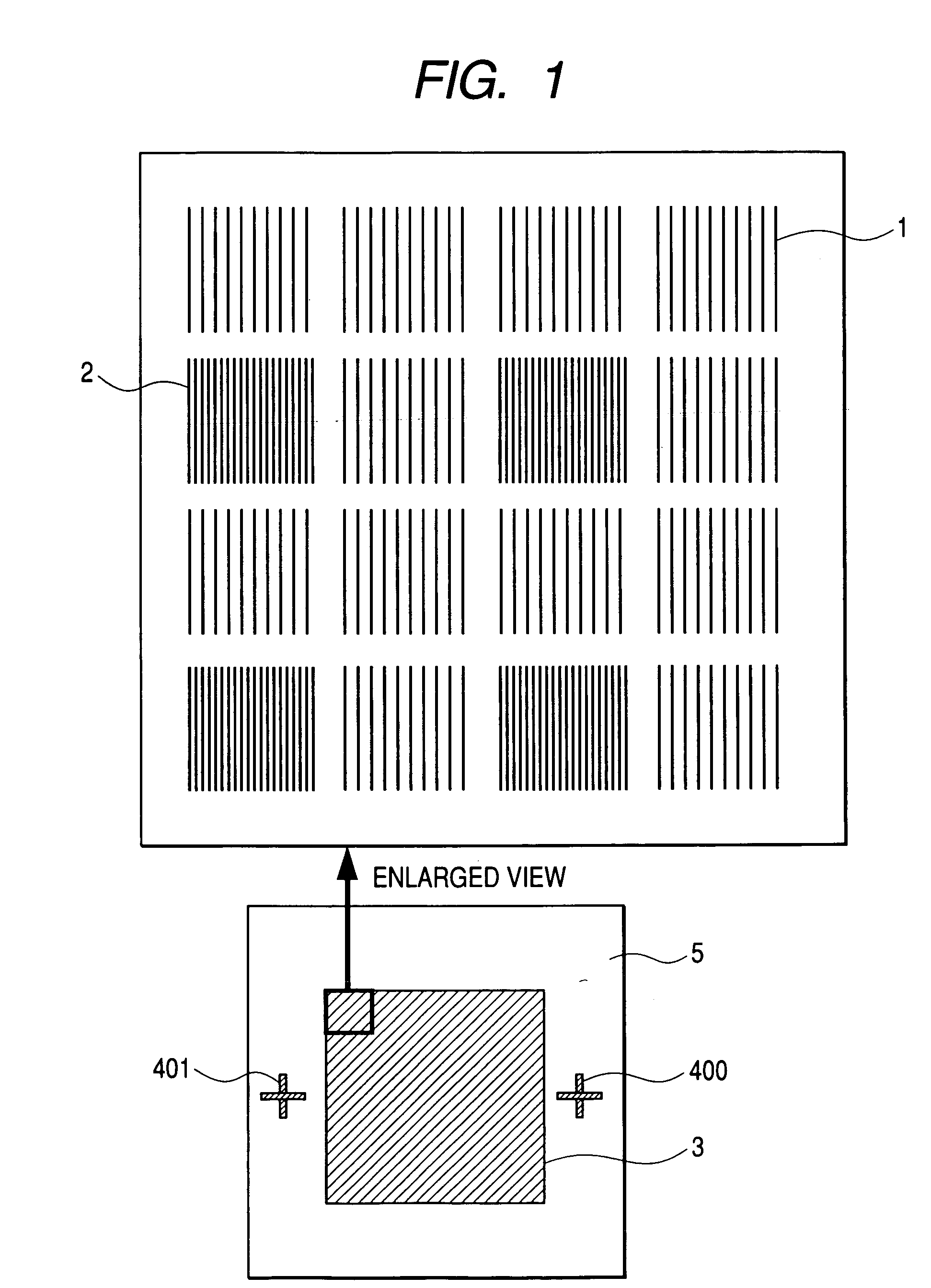
[0039]FIG. 1 through FIG. 5 show one example of standard reference for beam metrology according to the invention. FIG. 6 shows an example of standard reference for metrology for an electron-beam metrology system according to the prior art.

[0040] Conventionally, the trench pattern of unevenness on the semiconductor substrate of orientation (110) is prepared as a grating pattern 28 in a fixed direction by laser interferometer lithography and wet etching as shown in FIG. 6. The pitch of the grating pattern 28 is about 200 nm, and this value is obtained by diffraction angle measurement using a laser. The grating pattern 28 is formed all over a standard reference substrate 27 of 4 mm square. Calibration of an electron-beam metrology system using this reference substrate would involve the following problems.

[0041] The first problem concerns fineness. The lates...


PUM


Abstract

The present invention is to provide a standard reference for metrology having finer reference sizes and high-precision electron-beam metrology including the same. By using a standard reference member in which a grating unit pattern of a pitch size proven by an optical diffraction angle by using a laser beam whose wavelength is absolutely guaranteed and a plurality of patterns having a finer size than that (100 nm or less) over the same substrate, fineness and correctness of calibration are made verifiable on a regular basis, and by using an electron-beam collective exposure method for pattern fabrication, fabrication of this standard reference is made possible.

Description


Claims


Application Information

Patent Timeline
Owner HITACHI HIGH-TECH CORP
Why Eureka
Try Eureka