Sheet feeding apparatus

a technology of feeding apparatus and record sheet, which is applied in the direction of transportation and packaging, article separation, thin material processing, etc., can solve the problem of double feeding of the second record sheet, and achieve the effect of stabilizing the operation of feeding the record sheet and alleviating the load

Inactive Publication Date: 2005-08-25
FUJIFILM BUSINESS INNOVATION CORP
View PDF9 Cites 29 Cited by
  • Summary
  • Abstract
  • Description
  • Claims
  • Application Information

AI Technical Summary

Benefits of technology

[0025] According to the invention configured as described above, even when a kind or a thickness of the record sheet to be transported is changed, double feeding of the record sheets can firmly be prevented from the record sheet fed first by immediately detecting whether the separating force operated to the record sheet is sufficient with regard to the record sheet being fed and

Problems solved by technology

Further, it is found that when the advancing speed of the second record sheet is slow, the first record sheet and the second record sheet are normally separated, conversely, the faster

Method used


Image

  • Sheet feeding apparatus
  • Sheet feeding apparatus
  • Sheet feeding apparatus

Examples


first embodiment

[0075] A first embodiment of the invention will be explained as follows.

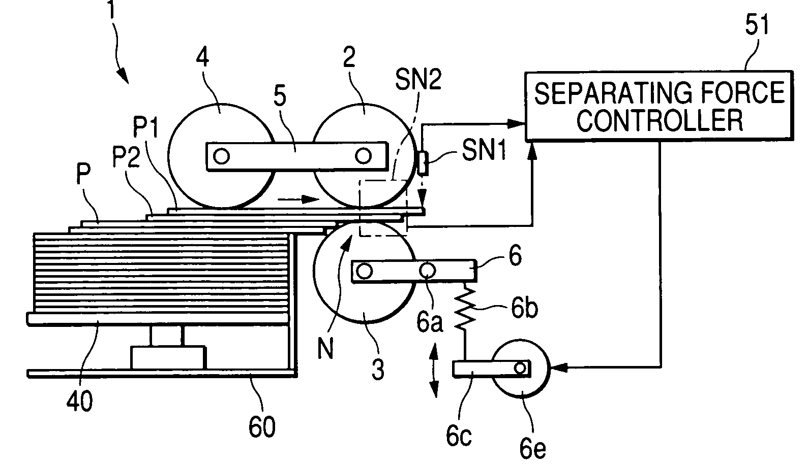
[0076] According to the first embodiment, there is arranged a double feeding degree detecting sensor SN 2 for detecting whether a second record sheet P2 is doubly fed to the nip portion N by being overlapped with a first record sheet P1 to be transported between the nip portion N and a detecting position of the sheet sensor SN 1. As shown in FIG. 4, the double feeding degree detecting sensor SN 2 is configured by a base member 52 brought into contact with a surface of the first record sheet P1 on a downstream side of the feeding roller 2 in a direction of feeding the record sheet P, a pivotable detecting arm 53 a front end of which is urged to the base member 52, and an encoder (not illustrated) for detecting a pivoting angle of the detecting arm. The detecting arm 53 is pivotably supported by a supporting shaft 54, and in a state in which the record sheet P does not pass the nip portion N, the front end of the...

second embodiment

[0105] A second embodiment of the invention will be explained as follows.

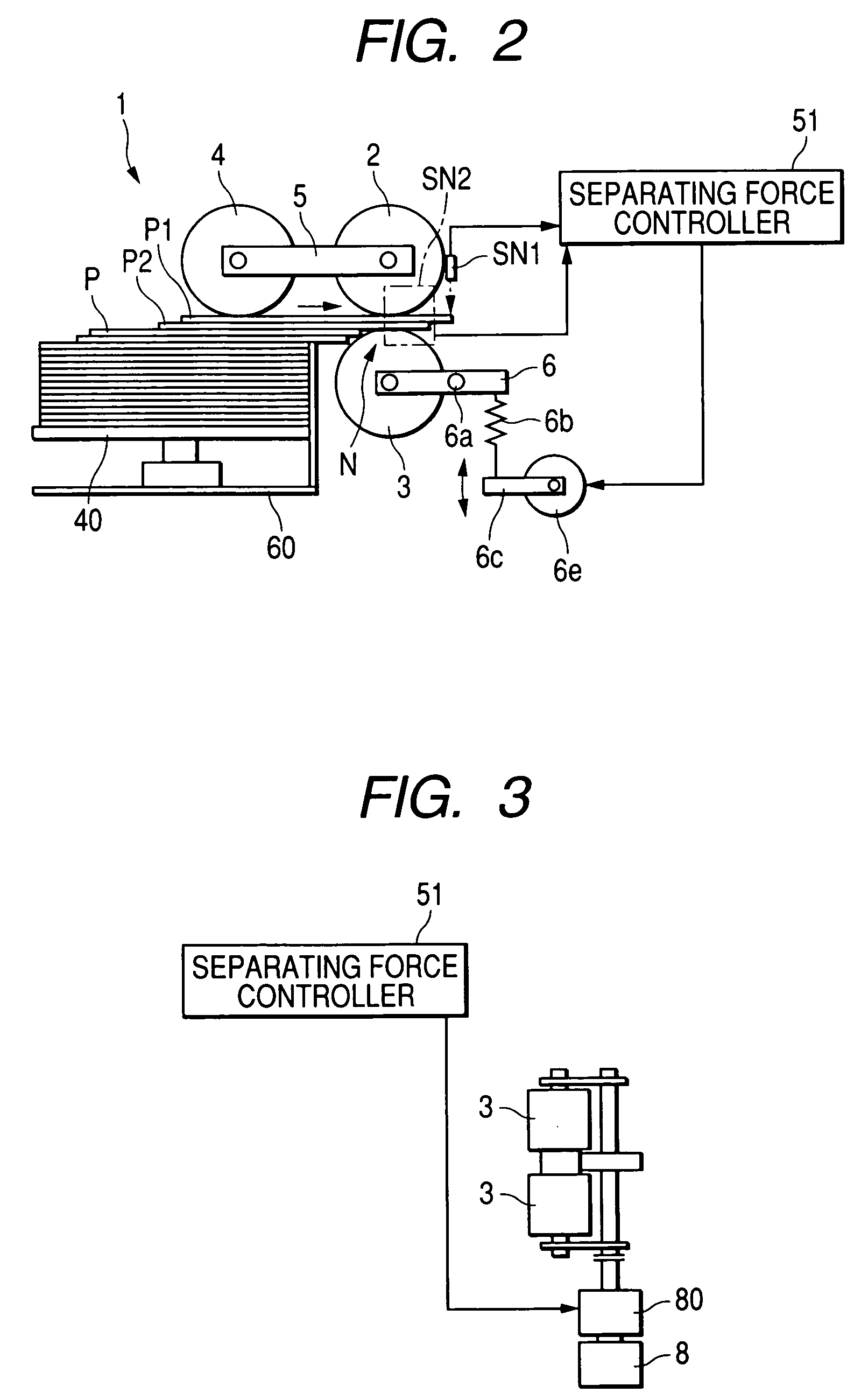
[0106] The second embodiment of the invention is configured such that a rotary encoder 3a is attached to the rotating shaft of the separating roller 3, and a speed operator 3b inputs an output signal of the rotary encoder 3a to detect the rotational speed of the separating roller 3. In the case in which in drawing out the record sheet P at inside of the discharge tray 60 by rotating the pickup roller 4 to transport to the nip portion N, the second record sheet P2 is also entered the nip portion by being dragged by the topmost record sheet (first record sheet) P1, when the second record sheet P2 is made to advance by being dragged by the first record sheet P1 at the nip portion N, the separating roller 3 is rotated in coincidence with advancement of the second record sheet P2. Therefore, when the rotational speed of the separating roller 3 is detected in this way, an advancing speed of the second record sheet P...


PUM


Abstract

There is provided a sheet feeding apparatus including a first feeding member that feeds at least one of the sheets from a discharge tray; a second feeding member that feeds the sheet fed by the first feeding member; a separating member, wherein a nip portion is formed between the separating member and the second feeding member, and when two sheets are entered the nip portion, the separating member separates one of the entered sheets from the other; an adjusting unit that changes a force of the separating member; a detecting unit that detects at least one of a distance by which the other of the entered sheets is transported beyond the nip portion and an advancing speed of the other of the entered sheets at the nip portion; and a controller that controls the adjusting unit based on a detection value of the detecting unit.

Description

BACKGROUND OF THE INVENTION [0001] 1. Field of the Invention [0002] The present invention relates to a sheet feeding apparatus for feeding record sheets such as a paper laminated on a discharge tray or a document tray to an image outputting portion or an image reading portion while separating the record sheets one-by-one in an image forming apparatus such as a copier, a facsimile, a printer or the like, in details relates to an improvement in a sheet feeding apparatus capable of arbitrarily adjusting a separating force exerted between a record sheet to be transported and a sheet fed doubly with the record sheet. [0003] 2. Description of the Related Art [0004] Conventionally, there is known a system for feeding record sheets laminated on a discharge tray while separating the record sheets one-by-one including a combination of a feeding roller and a separating roller applied with a reverse rotational torque. According to the system, a pickup roller is brought into contact with a topmo...

Claims


Application Information

Patent Timeline
IPC IPC(8): B65H3/06B65H3/52B65H7/08
CPCB65H3/5261B65H2511/222B65H2513/10B65H2515/32B65H2515/34B65H2220/01B65H2220/02
Inventor TSUKAMOTO, KAZUYUKITAKEUCHI, SHINSAKAMAKI, KATSUMI
Owner FUJIFILM BUSINESS INNOVATION CORP
Why Eureka
Try Eureka