
Portable information terminal controlling system and method

a technology of information terminal and control system, which is applied in the direction of assessing restriction, transportation and packaging, wireless communication, etc., can solve the problems of halting all the functions of the portable information terminal, limiting the display, and communication limitation, and achieve the effect of preventing traffic accidents

Inactive Publication Date: 2005-08-25
PANASONIC CORP
View PDF3 Cites 86 Cited by
  • Summary
  • Abstract
  • Description
  • Claims
  • Application Information

AI Technical Summary

Benefits of technology

[0010] According to the present structure, while the driver is driving the automobile, the function of the portable information terminal (for example, a cellular phone) in the automobile is limited; therefore, it contributes to prevent traffic accidents due to using the portable information terminal while driving. Items of the limitation include display limitation, communication limitation, and a halt of all the functions of the portable information terminal.
[0044] According to the present structure, a portable information terminal can be provided for use in the portable information terminal controlling system. Use of the portable information terminal as a part of the portable information terminal controlling system by the driver of the automobile will contribute to suppress traffic accidents due to operating the portable information terminal while driving.

Problems solved by technology

Items of the limitation include display limitation, communication limitation, and a halt of all the functions of the portable information terminal.
In the display limitation, display information on the display is limited by turning off the display of the portable information terminal or changing the image on the display screen into a fixed image.

Method used


Image

  • Portable information terminal controlling system and method
  • Portable information terminal controlling system and method
  • Portable information terminal controlling system and method

Examples


first embodiment

[0060] (First Embodiment)

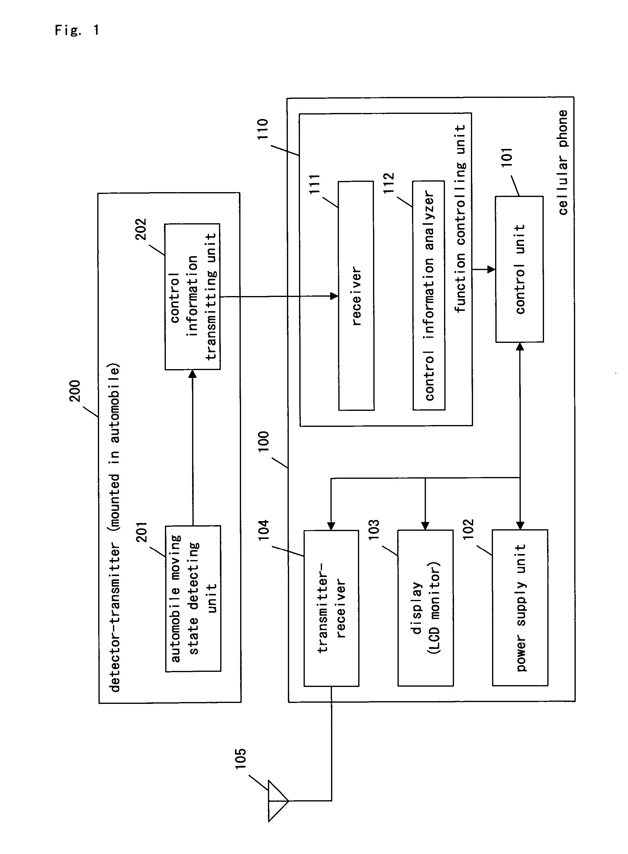
[0061]FIG. 1 is a block diagram of the portable information terminal controlling system in the first embodiment of the present invention. The portable information terminal controlling system of the present embodiment comprises a detector-transmitter 200 and a cellular phone 100. The detector-transmitter 200 possesses an automobile moving state detecting unit 201 and a control information transmitting unit 202. The cellular phone 100 possesses a function controlling unit 110, a control unit 101, a power supply unit 102, a display (for example, a LCD monitor) 103, a transmitter-receiver 104, and an antenna 105. The control unit 101, the power supply unit 102, the display 103, the transmitter-receiver 104, and the antenna 105 are basic components for the cellular phone 100 to perform regular communication.

[0062] The function controlling unit 110 includes a receiver 111 and a control information analyzer 112, and the output of the function controlling unit 110 ...

second embodiment

[0080] (Second Embodiment)

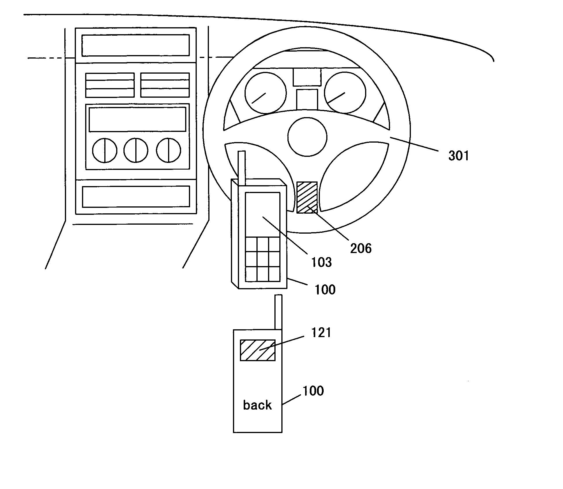
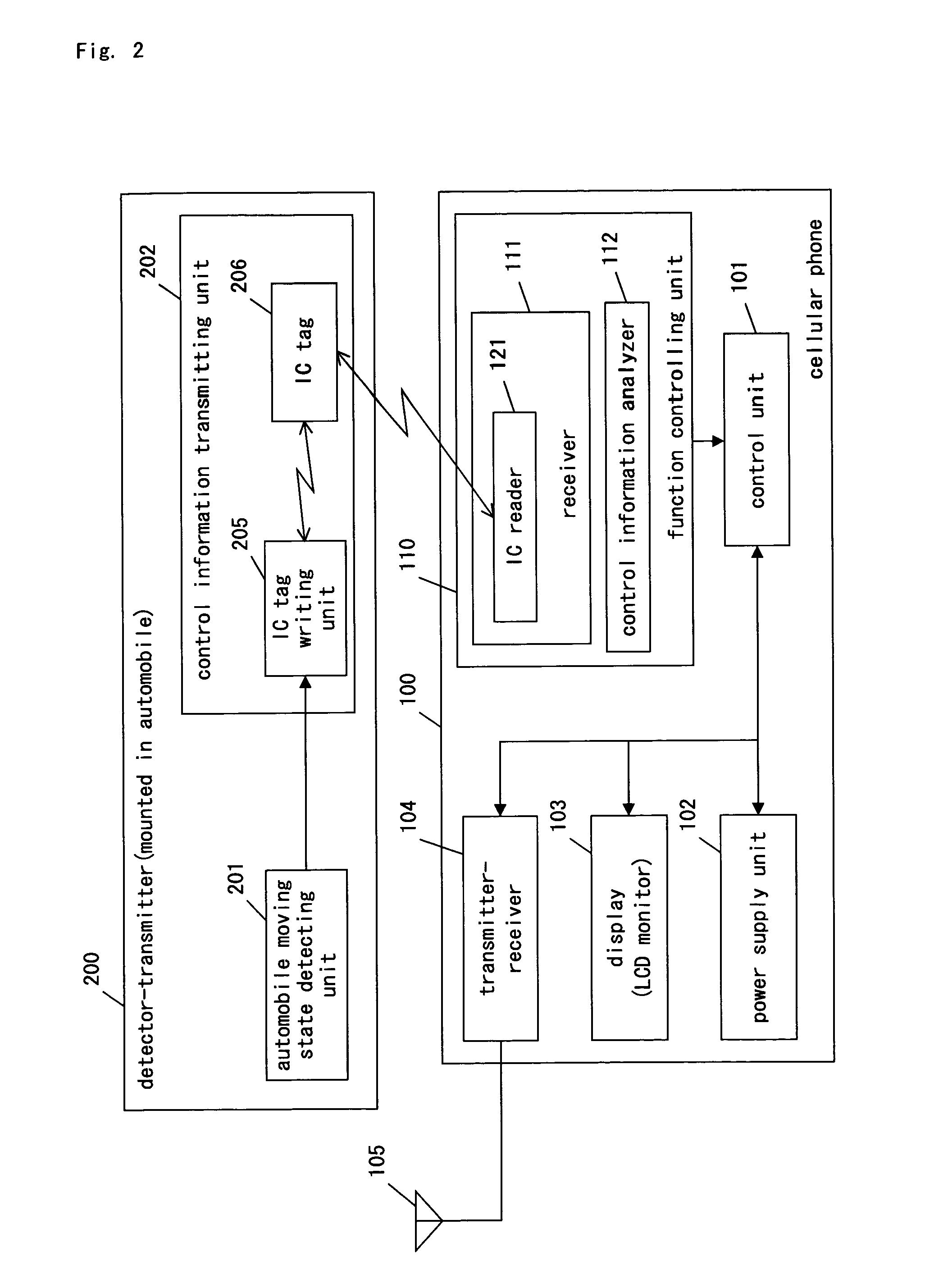
[0081] The portable information terminal controlling system of the second embodiment uses RFID (Radio Frequency Identification System: radio recognition system) for communication between the detector-transmitter 200 and the cellular phone 100. RFID is a wireless access system used for reading information from an IC card or a bar code. A communication distance of RFID is several tens centimeters because RFID performs communication with a very small power at frequencies of 13.56 MHz band, 2.45 GHz band or 5 GHz band.

[0082]FIG. 2 is the block diagram of the portable information terminal controlling system in the second embodiment of the present invention. In FIG. 2, regarding the same components as in FIG. 1, the same symbols are given and explanation thereof is omitted. Hereinafter, explanation is made referring to FIG. 2.

[0083] In the present embodiment, the control information transmitting unit 202 of the detector-transmitter 200 comprises an IC tag writi...

third embodiment

[0093] (Third Embodiment)

[0094] In a portable information terminal controlling system according to a third embodiment, an IrDA art is used for communication between the detector-transmitter 200 and the cellular phone 100. The IrDA art is a wireless communication art proposed by the Infrared Data Association.

[0095]FIG. 4 is a block diagram illustrating the portable information terminal controlling system according to the third embodiment of the present invention. In FIG. 4, regarding the same components as in FIG. 1, the same symbols are given and explanation thereof is omitted.

[0096] As illustrated in FIG. 4, in the present embodiment, the control information transmitting unit 202 of the detector-transmitter 200 includes an infrared transmitter 211. The infrared transmitter 211 is equivalent to the transmitting unit of the present invention. The infrared transmitter 211 is installed at a place in front of a driver's seat and far from a passenger seat.

[0097] The receiver 111 of th...


PUM


Abstract

A portable information terminal controlling system of the present invention comprises the detector-transmitter and the cellular phone. The detector-transmitter includes the automobile moving state detecting unit and the control information transmitting unit. The cellular phone includes the function controlling unit, the transmitter-receiver, the display and the control unit. When the detector-transmitter detects that an automobile is moving, the detector-transmitter sends control information to a function controlling unit. When the detector-transmitter detects that an automobile is moving, the function controlling unit limits a part of a display function and a communication function of a portable information terminal, or limits all functions of the portable information terminal, and makes the portable information terminal be in a difficult state to use by giving an instruction to the control unit. Judgment of the driver's use of the portable information terminal is performed based on a signal arriving time and signal strength between the detector-transmitter and the function controlling unit, or an image extract with a camera included in the detector-transmitter.

Description

BACKGROUND OF THE INVENTION [0001] 1. Field of the Invention [0002] The present invention relates to a portable information terminal controlling system that limits usage of a portable information terminal while a driver is driving an automobile, and related art thereto. [0003] 2. Description of the Related Art [0004] Traffic accidents due to usage of cellular phones while drivers are driving automobiles have been increasing as cellular phones spread out, and it has become a social issue. In order to solve the issue from technical side, a lot of methods are proposed to limit usage of cellular phones while driving automobiles. [0005] For example, reference 1 (published Japanese patent application H10-24808) discloses an art, which detects a moving state of an automobile and halts calling function of a driver's cellular phone when the state is judged as driving. [0006] Reference 2 (Published Japanese patent application No. 2000-349895) discloses an art, which detects whether or not an ...

Claims


Application Information

Patent Timeline
IPC IPC(8): H04B1/38H04M1/00H04B1/40H04M1/60H04M1/66H04M1/667H04M1/725H04W48/04H04W84/10
CPCH04B1/3877H04M1/66H04M1/6075
Inventor TARUKI, MAIKONAKAMURA, TSUYOSHI
Owner PANASONIC CORP
Learn More