Inkjet recording apparatus

a recording apparatus and inkjet technology, applied in other printing apparatus, printing after-treatment, printing, etc., can solve the problems of ink to harden inside the head before ink, high energy, and large size of light source unit, so as to reduce the total luminous energy irradiated, and prevent the effect of ink bleeding

Inactive Publication Date: 2005-08-25
FUJIFILM CORP
View PDF14 Cites 25 Cited by
  • Summary
  • Abstract
  • Description
  • Claims
  • Application Information

AI Technical Summary

Benefits of technology

[0022] The present invention has been made in view of foregoing circumstances, and it is an object of the invention to provide an inkjet recording apparatus that can effectively prevent the ink from bleeding with a small total luminous energy, accordingly the light source unit can be compact and the head blockages can be prevented. Furthermore, it is another object of the invention to provide an inkjet recording apparatus that can determine the ink which is ejected from the head by the same optical system as that used to harden the ink.
[0024] According to the present invention, as the light is intensively irradiated onto the region where the bleeding of the ink would be conspicuous, it is possible to effectively prevent the bleeding of the ink and to reduce the total luminous energy irradiated onto the print medium.
[0026] Preferably, the light irradiating device includes a scanning device which scans the print medium in a width direction of the print medium with the light having a prescribed beam width; and the control device controls the light irradiating device to irradiate constant luminous energy, and controls the scanning device in such a manner that a scanning speed with respect to the region of the print medium where the bleeding of the ink would be conspicuous is slower than a scanning speed with respect to the other region of the print medium.
[0028] Alternatively, it is also preferable that the light irradiating device includes a scanning device which two-dimensionally scans the print medium in a width direction and a conveyance direction of the print medium with the light having a prescribed beam width; and the control device controls the light irradiating device to irradiate constant luminous energy, and controls the scanning device in such a manner that a scanning speed with respect to the region of the print medium where the bleeding of the ink would be conspicuous is slower than a scanning speed with respect to the other region of the print medium.
[0031] Alternatively, it is also preferable that the light irradiating device includes a scanning device which two-dimensionally scans the print medium in a width direction and a conveyance direction of the print medium with the light having a prescribed beam width; and the control device controls a scanning speed of the scanning device to be constant, and controls the light source of the light irradiating device in such a manner that the luminous energy irradiated onto the region of the print medium where the bleeding of the ink would be conspicuous is increased.
[0039] According to the present invention, it is possible to reduce the total luminous energy irradiated onto the print medium and effectively prevent the bleeding of the ink, since the light is intensively irradiated onto the region where the bleeding of the ink would be conspicuous, such as the edges of the solid print region, the edges of the line region, the isolated dots, the regions of high contrast, and the regions of large color variation. Furthermore, it is possible that the light source unit can be more compact and the head blockages can be prevented by restricting the total luminous energy.

Problems solved by technology

More specifically, the above-described conventional inkjet recording apparatuses irradiate UV light immediately after the ink has been ejected toward the print medium so that the ink is prevented from bleeding; however, they may involve the following problems.
When the UV light is to be irradiated onto the entire print region for causing the ink to harden, high energy is required and hence the light source unit can be large in size.
If the irradiation position of the UV light is brought close to the print position so that the ink can be prevented from bleeding, the diffuse reflected UV light may cause the ink to harden inside the head before the ink is ejected.
Thus, there is a possibility of head blockages.
(3) If a laser diode having good light emission efficiency is used in order to save energy in the inkjet recording apparatus, there is a possibility that the energy may not be sufficient to cause the ink to harden over the whole print medium depending on the speed of conveyance of the print medium, since the luminous energy emitted from the laser diode may be smaller than that from other devices, such as an electric discharge tube.

Method used


Image

  • Inkjet recording apparatus
  • Inkjet recording apparatus
  • Inkjet recording apparatus

Examples


Embodiment Construction

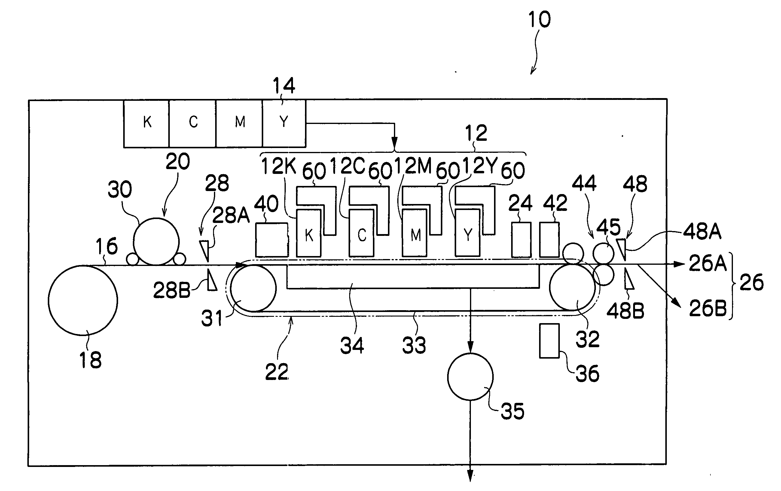
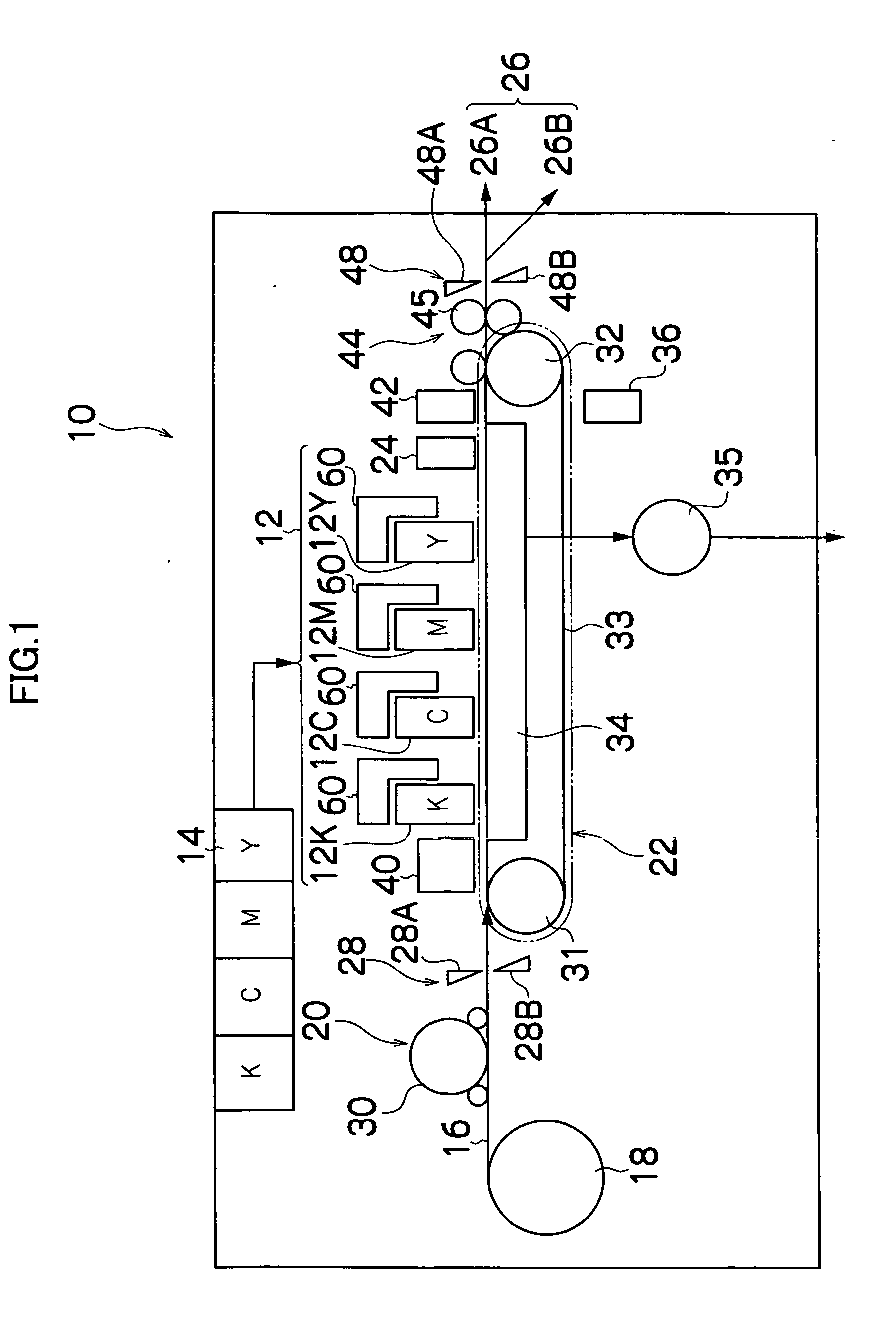
[0053] First, the description of an inkjet recording apparatus according to the present invention is explained. FIG. 1 is a general schematic drawing of an inkjet recording apparatus for forming an image by ejecting inks as droplet onto a recording medium, according to an embodiment of the present invention. As shown in FIG. 1, the inkjet recording apparatus 10 comprises: a printing unit 12 having a plurality of inkjet heads (hereinafter referred to as “head” simply) 12K, 12C, 12M, and 12Y for ink colors of black (K), cyan (C), magenta (M), and yellow (Y), respectively; an ink storing / loading unit 14 for storing inks to be supplied to the print heads 12K, 12C, 12M, and 12Y; a paper supply unit 18 for supplying recording paper 16; a decurling unit 20 for removing curl in the recording paper 16; a suction belt conveyance unit 22 disposed facing the nozzle face (ink-droplet ejection face) of the print unit 12, for conveying the recording paper 16 while keeping the recording paper 16 fl...


PUM


Abstract

The inkjet recording apparatus comprises: a head which ejects ink droplets of light-curable ink to a print medium to form an image on the print medium; a light irradiating device which is located at a downstream side of the head, and irradiates light from a light source onto the ink droplets immediately after the ink droplets have been deposited on the print medium; and a control device which controls the light irradiating device in such a manner that luminous energy irradiated onto a region of the print medium where bleeding of the ink droplets would be conspicuous is greater than luminous energy irradiated onto another region of the print medium.

Description

BACKGROUND OF THE INVENTION [0001] 1. Field of the Invention [0002] The present invention relates to an inkjet recording apparatus, and more particularly to a technology for preventing ink from bleeding. [0003] 2. Description of the Related Art [0004] Conventional printing processes are well known in which printing is carried out onto a print medium by employing an ultraviolet (UV) curable ink, and the ink is prevented from bleeding by causing the ink to harden by irradiating UV light onto the ink after the ink has been deposited on the print medium. [0005] Japanese Patent Application Publication No. 2003-11334 discloses a device in that a UV light source is arranged integrally with an ink ejecting head along the travel direction of the head. The ink ejected from the head is caused to harden by irradiating UV light from the UV light source onto the ink in a recorded region that has been recorded in the previous scan. [0006] Japanese Patent Application Publication No. 2003-11343 disc...

Claims


Application Information

Patent Timeline
Patent Type & Authority Applications(United States)
IPC IPC(8): B41J2/01B41J11/00
CPCB41J11/002B41M7/0081B41J11/00212B41J11/00214B41J11/00216
Inventor NAGASHIMA, KANJI
Owner FUJIFILM CORP
Why Eureka
Try Eureka