Light modulation device and optical display device, and light modulation method and image display method

a technology which is applied in the field of light modulation device and optical display device, and light modulation method and image display method, can solve the problems of perceived insufficiency with regard to reality, inability to provide a display, and deterioration of the luminance of the displayed image, so as to enhance the luminance of the display image and the picture quality, the effect of increasing the luminance dynamic range and the number of gradations

Inactive Publication Date: 2005-08-25
SEIKO EPSON CORP
View PDF3 Cites 16 Cited by
  • Summary
  • Abstract
  • Description
  • Claims
  • Application Information

AI Technical Summary

Benefits of technology

[0027] Thus, the present invention has been made in order to address the unsolved problems associated with this type of conventional art technique and, therefore, it takes as its objective to provide a light modulation device and an optical display device, and a light modulation method

Problems solved by technology

When a display image of a current optical display device is viewed via this type of human visual characteristic, the narrowness of the luminance dynamic range is conspicuous, and furthermore there is a perceived insufficiency with regard to the reality of the display image and its impact, since the gradations of the shadow portions and the highlight portions are insufficient.
However there is the problem that, since the performance of the optical display device upon which this data is to be displayed is insufficient, it is not possible to provide a display which exhibits the CG contents with the power of expression that they originally had.
In this structure, there has been the problem that the luminance of the displayed image is deteriorated.
However, due to its very high definition, a current light modulation element (for example, a liquid crystal light valve) has a picture element

Method used


Image

  • Light modulation device and optical display device, and light modulation method and image display method
  • Light modulation device and optical display device, and light modulation method and image display method
  • Light modulation device and optical display device, and light modulation method and image display method

Examples


Embodiment Construction

[0130] In the following, various preferred embodiments of the present invention will be described with reference to the drawings.

[0131] These preferred embodiments are ones in which the light modulation device, the optical display device, the light modulation method, and the image display method of the present invention are applied to a projection type display device.

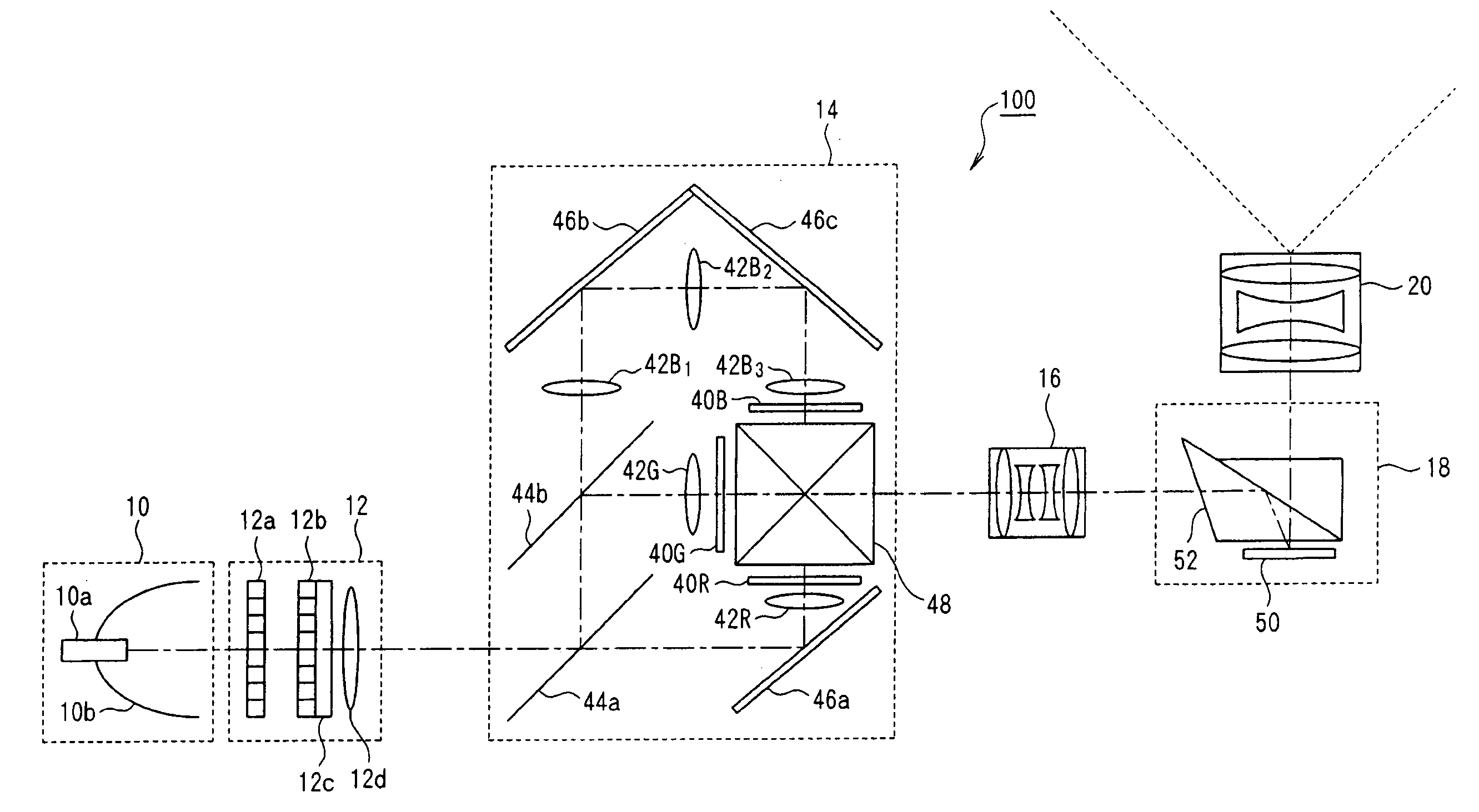
[0132] The structure of a projection type display device 100 which incorporates the first preferred embodiment of the present invention will now be explained with reference to FIG. 1. FIG. 1 is a block diagram showing the hardware structure of this projection type display device 100.

[0133] This projection type display device 100, as shown in FIG. 1, comprises a light source 10, a luminance distribution uniformalization section 12, which makes uniform the luminance distribution of the light which is incident upon it from the light source 10, a color modulation section 14 which modulates the individual luminances in th...


PUM


Abstract

A projection type display device includes dichroic mirrors which separate the light from the light source into light of the three primary colors R, G and B, a plurality of color modulation light valves upon which the light beams separated by the dichroic mirrors are respectively incident and comprising a plurality of picture elements which are capable of being individually controlled with regard to their transmittivity ratios, a dichroic prism which combines the light beams from the color modulation light valves, a relay lens which forms the optical images of the color modulation light valves upon the picture element surface of a reflective type liquid crystal light valve, and a reflective type liquid crystal light valve upon which the light from the relay lens is incident and comprising a plurality of picture elements whose reflectivity ratios can be individually controlled.

Description

BACKGROUND OF THE INVENTION [0001] 1. Field of the Invention [0002] The present invention relates to a device and a method for modulating the light from a light source via a plurality of light modulation elements. In particular, the present invention relates to a light modulation device and optical display device, and light modulation method and image display method, which are appropriate for implementing widening of the luminance dynamic range and number of gradations, for enhancing the luminance of the displayed images and their picture quality, and for making the entire device more compact. [0003] Priority is claimed on Japanese Patent Application No. 2004-35091 filed 12 Feb. 2004, Japanese Patent Application No. 2004-48015 filed 24 Feb. 2004, and Japanese Patent Application No. 2004-54185 filed 27 Feb. 2004, the contents of which are incorporated herein by reference. [0004] 2. Description of Related Art [0005] In recent years, the improvement in the picture quality of optical di...

Claims


Application Information

Patent Timeline
IPC IPC(8): G02B13/00
CPCG02B13/0095
Inventor UCHIYAMA, SHOICHINAKAMURA, JUNICHINITTA, TAKASHIASAHI, TSUNEMORI
Owner SEIKO EPSON CORP
Why Eureka
Try Eureka