Camera and photographing lens barrel
a technology for photographing and camera, applied in the field of camera and photographing lens barrel, can solve the problems of increasing the diameter of the metal cylindrical member, difficult attachment, and design limitations, and achieve the effect of reducing design limitations
- Summary
- Abstract
- Description
- Claims
- Application Information
AI Technical Summary
Benefits of technology
Problems solved by technology
Method used
Image
Examples
first embodiment
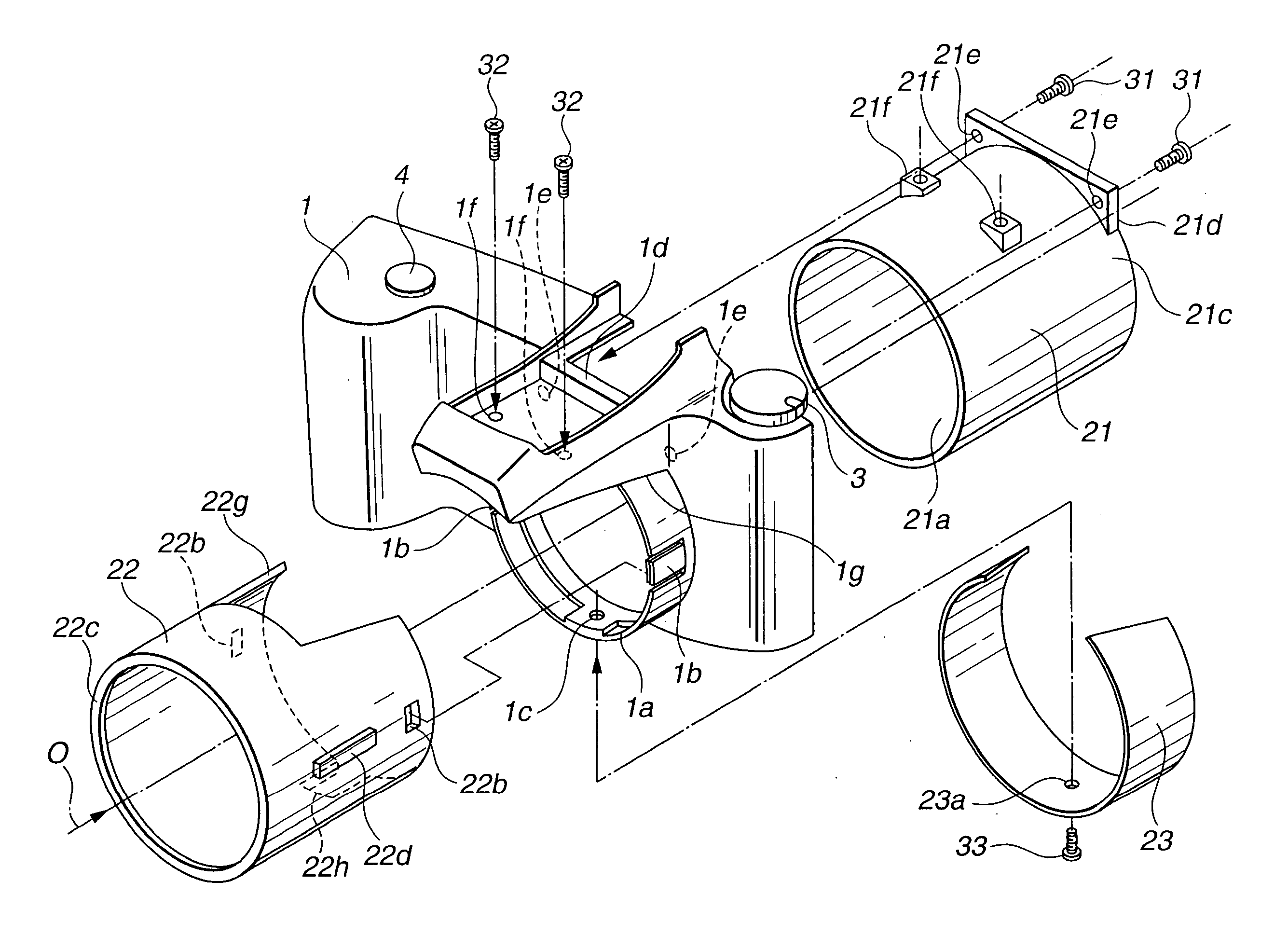
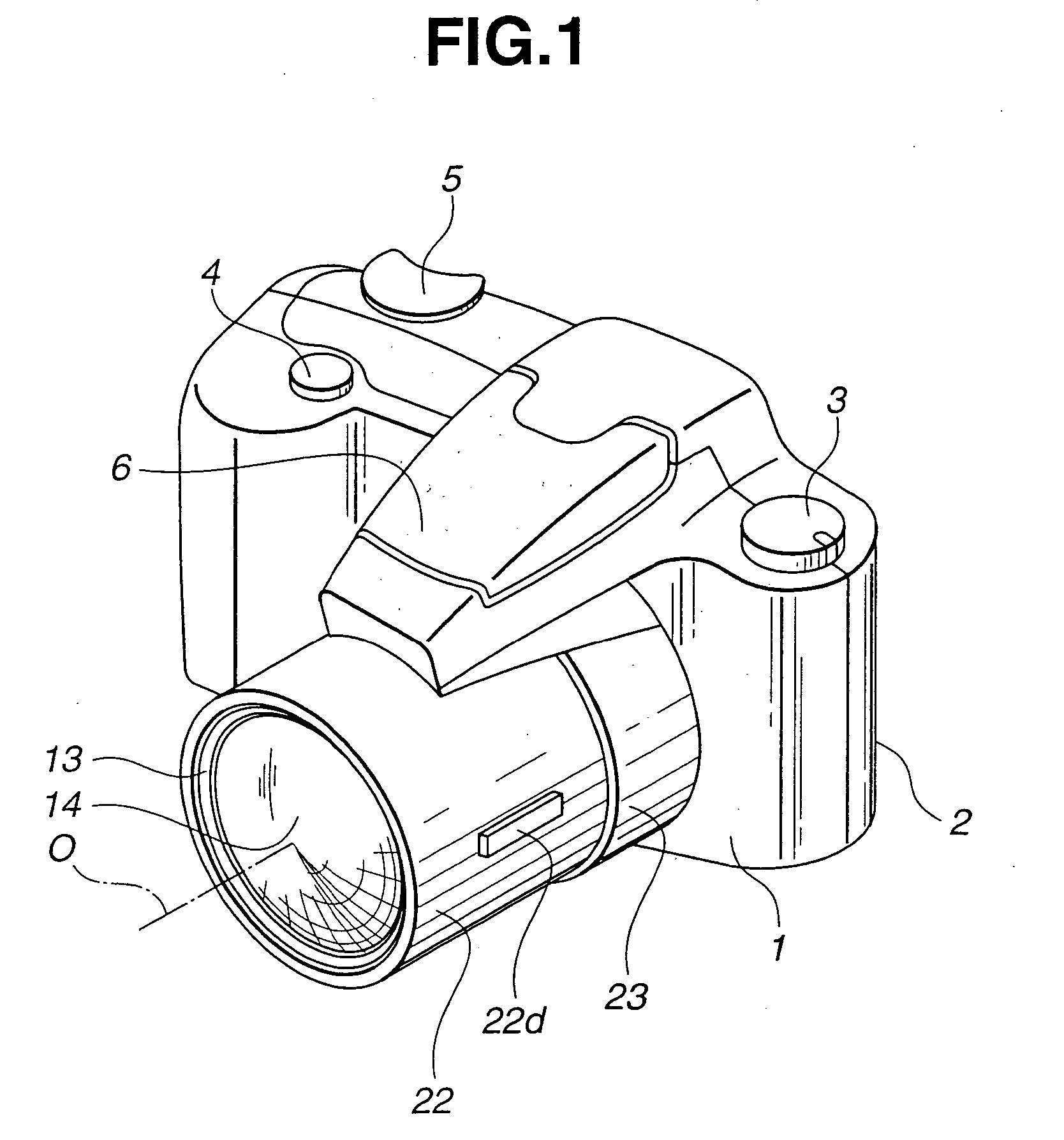
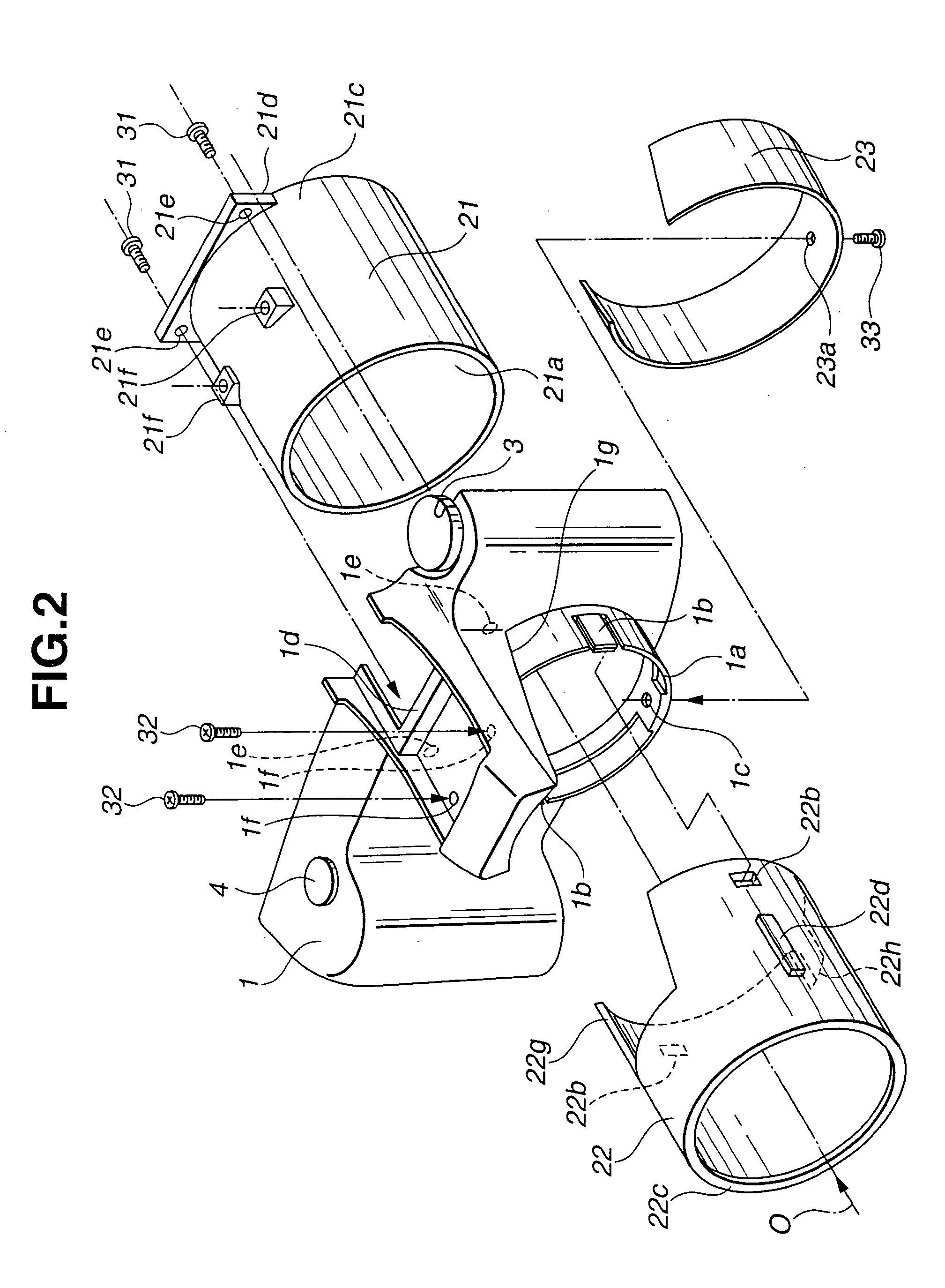
[0096]FIG. 1 is a an externally perspective view showing a camera according to the present invention. FIG. 2 is an exploded perspective view showing an exterior portion around a lens barrel unit of the camera. FIG. 3 is a longitudinal cross-sectional view around the lens barrel unit of the camera. FIG. 4 is a horizontally cross-sectional view around the lens barrel unit of the camera. In the following description, a subject side of the camera is in front and an image forming side is in the back.
[0097] Referring to FIG. 1, an exterior portion of the camera according to the first embodiment comprises: a front cover 1 and a rear cover 2, as members for covering a camera main body unit 11 (refer to FIG. 3) and as second members (second cylindrical members); an exterior cylindrical member 22 made of metal as a third member (first cylindrical member); and a stop-portion cover 23 as a cover member.
[0098] The front cover 1 comprises: a release button 3; a pop-up strobe light emitting porti...
second embodiment
[0116] Next, a description is given of a lens barrel according to the present invention.
[0117]FIG. 5 is an exploded perspective view showing two lens-group frames incorporated in the lens barrel according to the second embodiment. FIG. 6 is a longitudinal cross-sectional view when the two lens-group frames are engaged with each other. FIG. 7 is a longitudinal cross-sectional view when the two lens-group frames incorporated in the lens barrel are set apart from each other.
[0118] The lens barrel according to the second embodiment comprises four groups of lenses. Referring to FIG. 5, the lens barrel includes a third-group frame 41 as a first frame member which advances and returns upon zooming, a fourth-group frame 42 as a second frame member, and a first-group frame and a second-group frame (not shown).
[0119] The third-group frame 41 has a guide shaft hole 41a at the bottom of the frame, two cam followers 46 and 47 fixed at the top of the frame, and an engaging piece 41b having a cl...
third embodiment
[0131] Next, a description is given of a lens barrel according to the present invention.
[0132]FIG. 8 is a perspective view showing an engaging state of two lens-group frames incorporated in a lens barrel according to the third embodiment. FIG. 9 is a perspective view showing an apart state of the two lens-group frames incorporated in the lens barrel. FIG. 10 is a longitudinally cross-sectional view showing a state in which the two engaged lens-group frames are attached to a lens center adjusting device. FIG. 11 is a longitudinally cross-sectional view showing a state in which the two lens-group frames are incorporated in the lens barrel.
[0133] Referring to FIG. 8, the lens barrel according to the third embodiment comprises four groups of lenses, and incorporates, as a photographing optical system, a third-group frame 61 as a first frame member which can advance and return, a fourth-group frame 62 as a second frame member, and a first-group frame and a second-group frame (not shown)...
PUM
 Abstract
Description
Claims
Application Information
 - R&D
- Intellectual Property
- Life Sciences
- Materials
- Tech Scout
- Unparalleled Data Quality
- Higher Quality Content
- 60% Fewer Hallucinations
Browse by: Latest US Patents, China's latest patents, Technical Efficacy Thesaurus, Application Domain, Technology Topic, Popular Technical Reports.
© 2025 PatSnap. All rights reserved.Legal|Privacy policy|Modern Slavery Act Transparency Statement|Sitemap|About US| Contact US: help@patsnap.com


