Condition management callback system and method of operation thereof

a callback system and condition management technology, applied in the field of processors, can solve the problems of inefficient polling, increasing the amount of computer time consumed by polling, and increasing the complexity of tasks and the number of devices

Inactive Publication Date: 2005-08-25
AVAGO TECH INT SALES PTE LTD
View PDF3 Cites 13 Cited by
  • Summary
  • Abstract
  • Description
  • Claims
  • Application Information

AI Technical Summary

Problems solved by technology

While effective for simple tasks involving a relatively small number of devices, polling came to consume ever-greater amounts of the computer's time as the tasks and the numbers of devices became more complex.
Polling is inefficient, because the computer must poll even when no conditions requiring the computer's response have occurred.
At its extreme, polling may even consume so much time that the computer is precluded from performing other tasks.
With interrupts, the computer does not actively determine the condition of external devices.
Interrupts are widely used today, but they are by no means a perfect solution.
Interrupt handling becomes complex when a computer is called upon to sense and control a great number of exter...

Method used


Image

  • Condition management callback system and method of operation thereof
  • Condition management callback system and method of operation thereof
  • Condition management callback system and method of operation thereof

Examples


Embodiment Construction

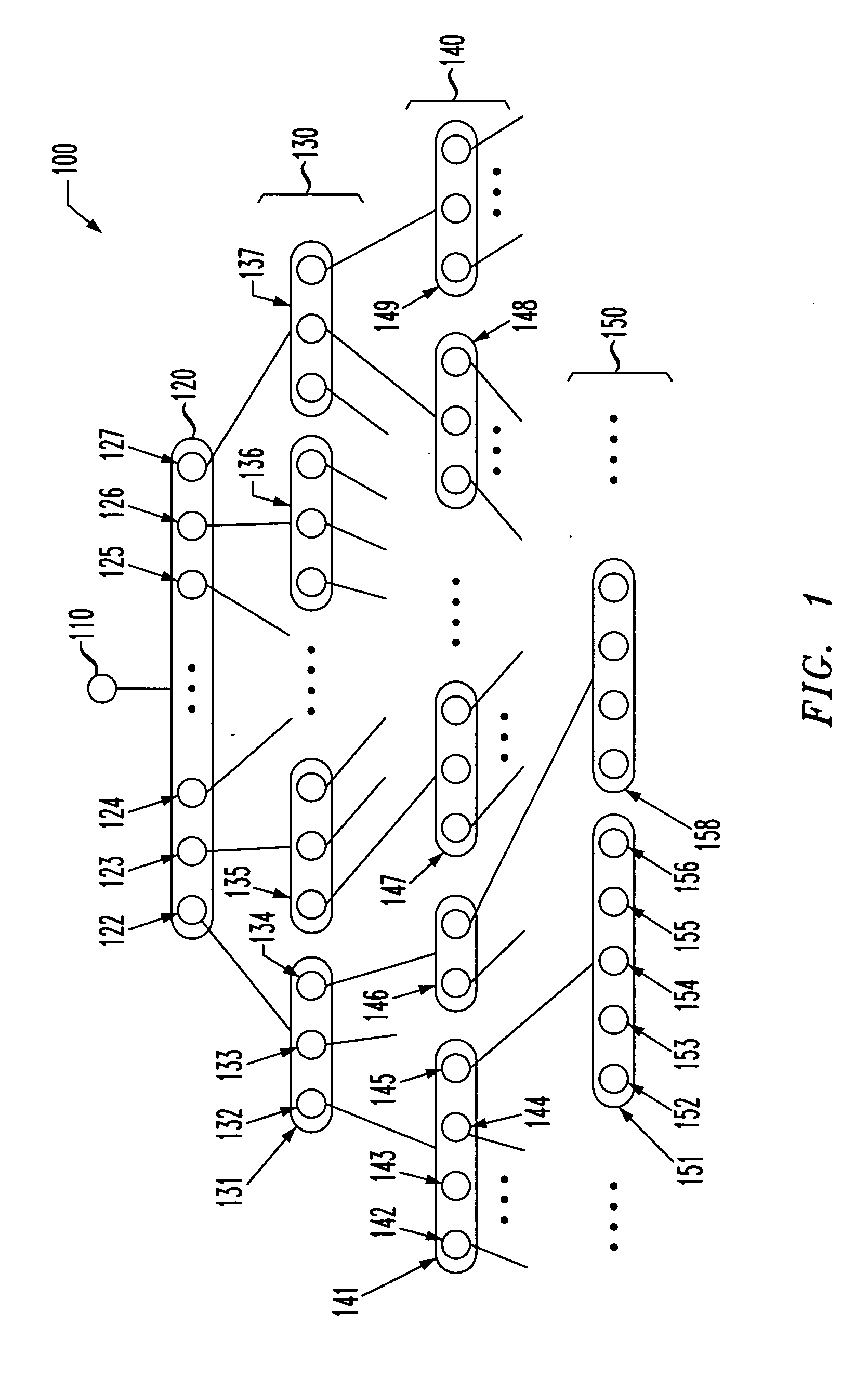
[0019] Referring initially to FIG. 1, illustrated is a schematic diagram of an example of a hierarchical register consolidation structure, generally designated 100, of a processor that may be employed by the present invention. The hierarchical register consolidation structure 100 has a structure similar to a tree structure having branches and leaves.

[0020] The lowest level of registers (leaves) in the hierarchical register consolidation structure 100 contains source-level interrupts 150. In the illustrated embodiment, the source-level interrupts 150 handle all of the alarms or events associated with the physical circuitry of or connected to the processor. The source-level interrupts 150 include a plurality of alarm registers 151, 158. The alarm registers 151, 158 are typically a “write-1-clear” register having bits 152-156 for each alarm (or event) associated therewith. A “write-1-clear” register latches each of the alarm bits, such as the alarm bits 152-156, until cleared. Also, o...


PUM


Abstract

A condition management callback system and method for use with a processor employing a hierarchical register consolidation structure. In one embodiment, the system includes: (1) a condition management structure, (2) a callback abstraction subsystem configured to register a callback for at least one element object in the condition management structure and store logically abstracted data associated with the callback and (3) an abstraction retrieval subsystem configured to employ the condition management structure to determine a condition of at least one status indicator in the condition management structure by traversing the hierarchical register consolidation structure, initiate the callback based on the condition and pass the logically abstracted data if the element object representing the status indicator has the callback registered.

Description

CROSS-REFERENCE TO RELATED APPLICATION [0001] This application is related to U.S. patent application Ser. No. ______ [Attorney Docket No. AGER-124436] entitled “A Condition Management System and Method of Operation Thereof” to Eckhart, et al., filed on ______, 2003, which is commonly assigned with the present invention and incorporated herein by reference as if reproduced herein in its entirety.TECHNICAL FIELD OF THE INVENTION [0002] The present invention is directed, in general, to processors and, more specifically, to a condition management callback system for use with a processor and a method of operation of a condition management callback system. LIMITED COPYRIGHT WAIVER [0003] A portion of the disclosure of this patent document contains material to which the claim of copyright protection is made. The copyright owner has no objection to the facsimile reproduction by any person of the patent document or the patent disclosure, as it appears in the U.S. Patent and Trademark Office ...

Claims


Application Information

Patent Timeline
IPC IPC(8): G06F13/24
CPCG06F13/24
Inventor HITCHCOCK, RUSSELLHOLMES, MICHAEL A.KAHN, KEITHWILLIAMS, GERALD S.
Owner AVAGO TECH INT SALES PTE LTD
Why Eureka
Try Eureka