Methods and apparatus for processor task migration in a multi-processor system

a multi-processor system and processor technology, applied in the direction of multi-programming arrangements, instruments, program control, etc., can solve the problems of programmers not optimizing the allocation of processor tasks among sub-processing units, application requirements that require extremely fast processing speeds, and inability to generally match multi-processor architecture processing speeds

Active Publication Date: 2005-08-25
SONY COMPUTER ENTERTAINMENT INC
View PDF15 Cites 120 Cited by
  • Summary
  • Abstract
  • Description
  • Claims
  • Application Information

AI Technical Summary

Problems solved by technology

These applications require extremely fast processing speeds, such as many thousands of megabits of data per second.
While single processing units are capable of fast processing speeds, they cannot generally match the processing speeds of multi-processor architectures.
A drawback to this approach is that the programmer may not have optimized the allocation of processor tasks among the sub-processing units.
This dictates that some of the processor tasks be put on hold until the specified sub-processing unit becomes available, thereby delaying their execution.
Unfortunately this also results in an unpredictable latency as to the execution of the processor tasks.
Unfortunately communication protocols often result in message delays between the managing element and the sub-processing units.
Indeed, such protocols may require the use of a memory mapped I / O space (using memory mapped registers), which are generally slow.
Further, the managing elements (which may themselves be processors of the system) may employ multiple partition domains, which may require significant time to change (e.g., 700 us).
These characteristics also delay execution of the processor tasks and result in unpredictable latencies.
Thus, overall processor throughput and efficiency of the multi-processing system are sacrificed, which may result in significant impact on the real-time and / or multimedia experience of a user of the system.

Method used


Image

  • Methods and apparatus for processor task migration in a multi-processor system
  • Methods and apparatus for processor task migration in a multi-processor system
  • Methods and apparatus for processor task migration in a multi-processor system

Examples


Embodiment Construction

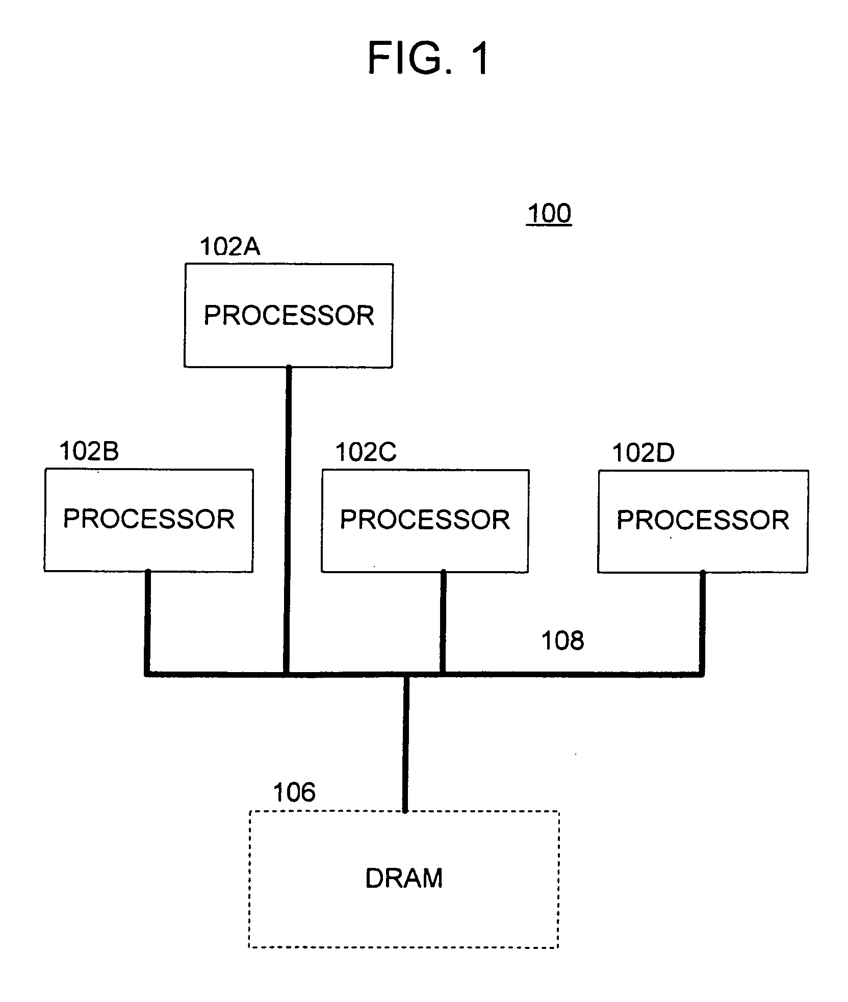
[0060] With reference to the drawings, where like numerals indicate like elements, there is shown in FIG. 1 a multi-processing system 100 in accordance with one or more aspects of the present invention. The multi-processing system 100 includes a plurality of processors 102 (any number may be used) coupled to a shared memory 106, such as a DRAM, over a bus 108. It is noted that the shared memory 106 need not be a DRAM; indeed, it may be formed using any known or hereinafter developed technology.

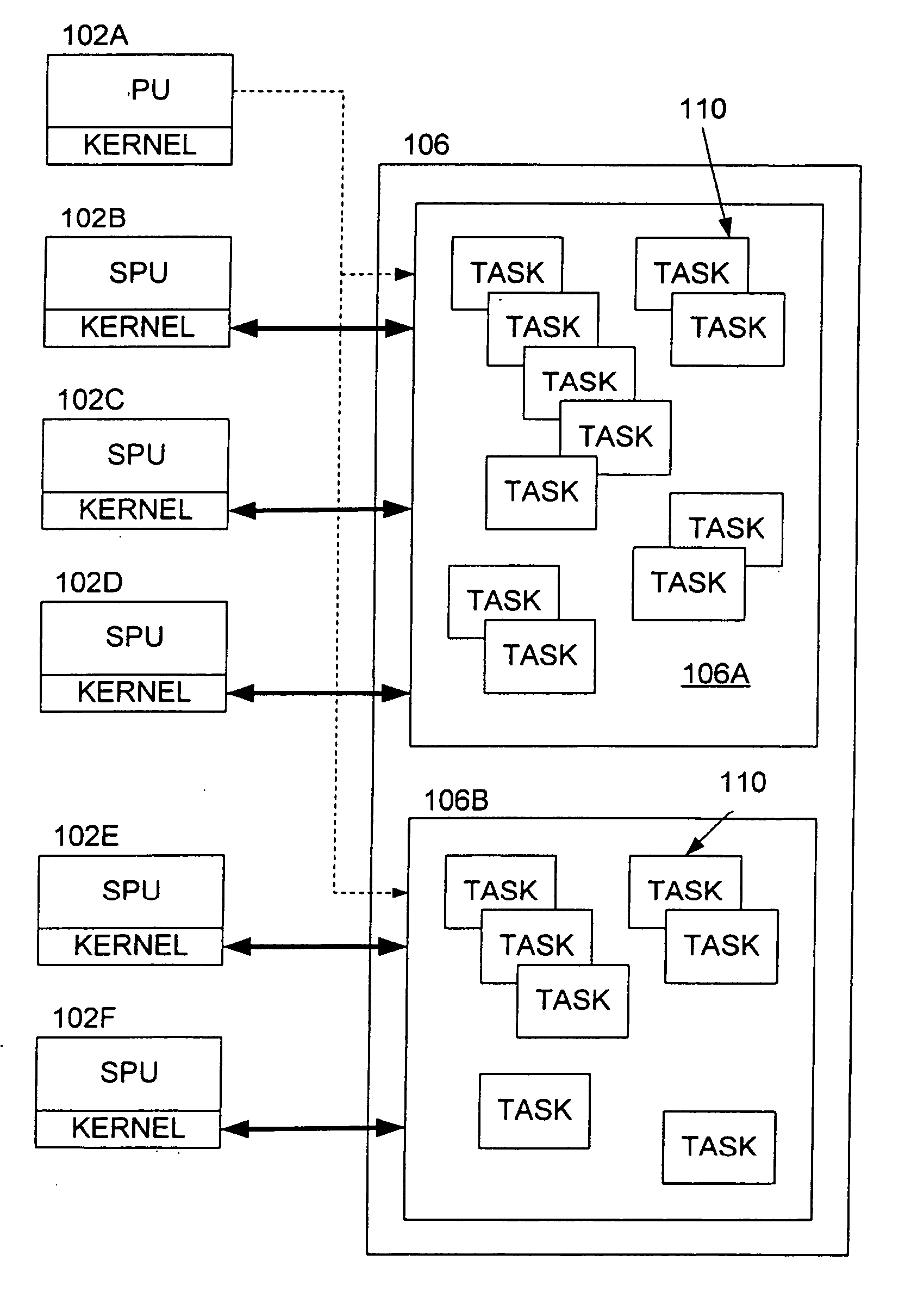
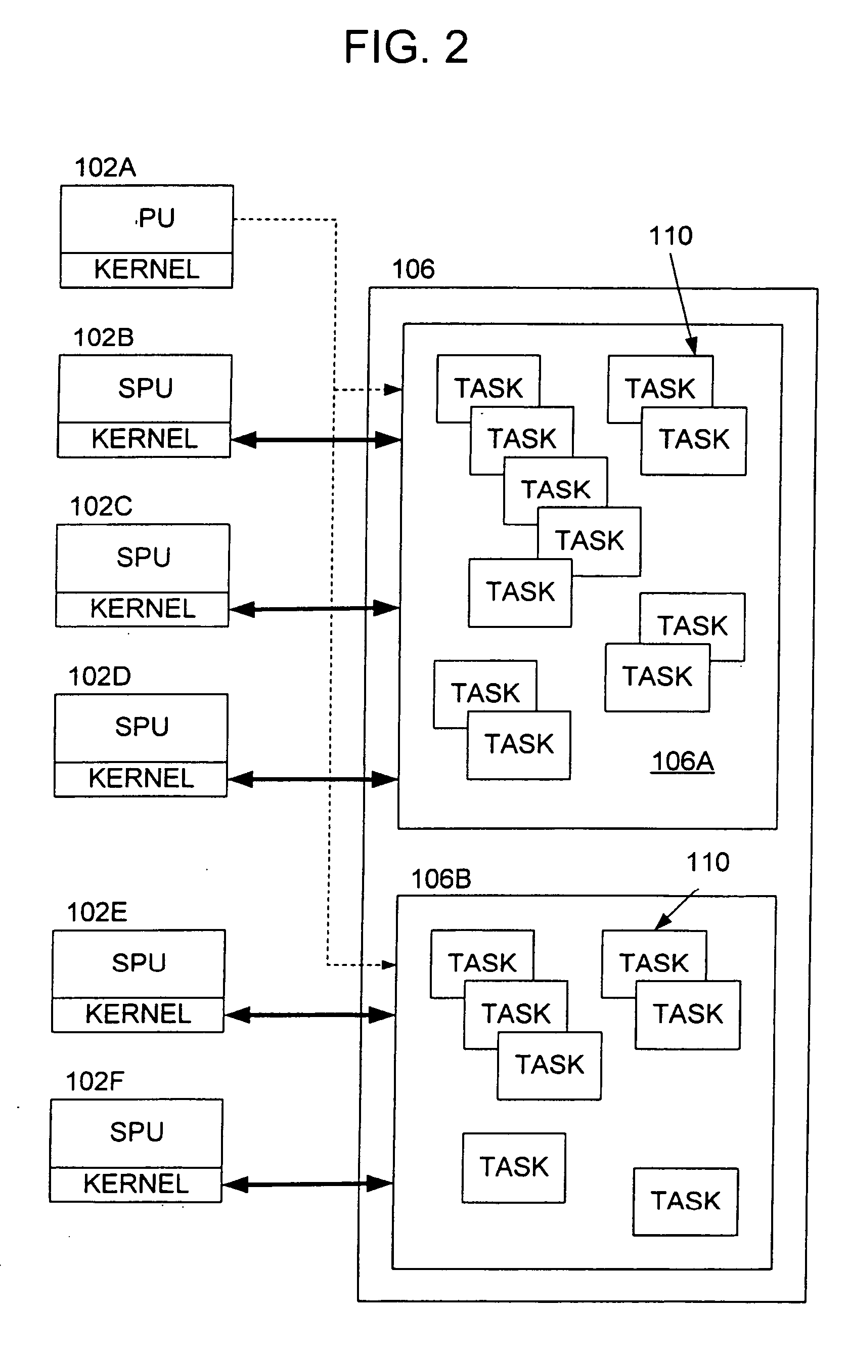
[0061] One of the processors 102 is preferably a main processing unit, for example, processing unit 102A. The other processing units 102 are preferably sub-processing units (SPUs), such as processing units 102B, 102C, 102D, etc. The sub-processing units 102 may be implemented using any of the known or hereinafter developed computer architectures. All of the sub-processing units 102 need not be implemented using the same architecture; indeed they may be of heterogeneous or homogenous configura...


PUM


Abstract

Methods and apparatus are provided for executing processor tasks on a multi-processing system. The multi-processing system includes a plurality of sub-processing units and a main processing unit that may access a shared memory. Each sub-processing unit includes an on-chip local memory separate from the shared memory. The methods and apparatus contemplate: providing that the processor tasks be copied from the shared memory into the local memory of the sub-processing units in order to execute them, and prohibiting the execution of the processor tasks from the shared memory; and migrating at least one processor task from one of the sub-processing units to another of the sub-processing units.

Description

BACKGROUND OF THE INVENTION [0001] The present invention relates to methods and apparatus for managing processor tasks in a multi-processing system and, in particular, for scheduling and executing the processor tasks among the sub-processing units of the multi-processing system on a substantially self governing basis. [0002] Real-time, multimedia applications are becoming increasingly important. These applications require extremely fast processing speeds, such as many thousands of megabits of data per second. While single processing units are capable of fast processing speeds, they cannot generally match the processing speeds of multi-processor architectures. Indeed, in multi-processor systems, a plurality of sub-processors can operate in parallel (or at least in concert) to achieve desired processing results. [0003] The types of computers and computing devices that may employ multi-processing techniques are extensive. In addition to personal computers (PCs) and servers, these compu...

Claims


Application Information

Patent Timeline
Patent Type & Authority Applications(United States)
IPC IPC(8): G06F9/445G06F9/48G06F9/46G06F9/50
CPCG06F9/4411G06F2209/5021G06F9/5038G06F9/4856G06F9/46G06F9/50G06F9/48
Inventor INOUE, KEISUKEIWAMOTO, TATSUYA
Owner SONY COMPUTER ENTERTAINMENT INC
Why Eureka
Try Eureka