[0011] In prior art systems, the requirements of these flows often interfere with each other. For example, in the
system of International Publication No. WO 98 / 28066, the flow of scouring bubbles and permeate occur in the same direction in the same space. As a result, holes for scouring bubbles are required in the lower header which reduce the number of hollow fibers that can be potted in the headers. Further, the top header is required to withdraw permeate which interferes with the flow of scouring air upwards through the module and encourages the bubbles to flow out of the module rather than rise all the way through it. Together, these factors also constrain the permissible depth of the module because of the pressure drop caused by flow through the
hollow fiber membrane. In the
system of International Publication No. WO01 / 36074, the direction of permeate flow is in the same space as, but perpendicular to, the flow of scouring air. This allows permeate to be withdrawn from both headers, if desired, without using complex headers, reduces air scouring as a factor effecting choice of membrane length, removes the headers from the flow path of scouring air and allows the scouring bubbles to be contained in vertical flow channels so that they do not flow out of the module. However, the flow of tank side water during deconcentration is in the same direction and space as the scouring air. While the system is still satisfactory, this creates competing objectives. In particular, to maximize the speed or efficiency of tank
water flow during deconcentration, and reduce the stress caused by this flow on the fibers, it is desirable to leave some passage through the vertical flow cannels, for example by
potting slackened fibers in bundles pulled together at the headers. However, scouring air bubbles are also inclined to flow through these passages which decreases their effectiveness and may create undesirable local
high velocity water flows by air lift effect during air scouring. Accordingly, the passages cannot be made too large. Further, although slackened fibers respond better to air scouring, the slackened fibers are also pulled into the passages by the deconcentration flows, decreasing the
effective size of the passages. Accordingly, the fibers may still be exposed to deconcentration flows at high velocity, for example in the range of 4 to 10 cm / s, which may stress the fibers, limit allowable fiber length or require the use of a strong, typically expensive, fiber.
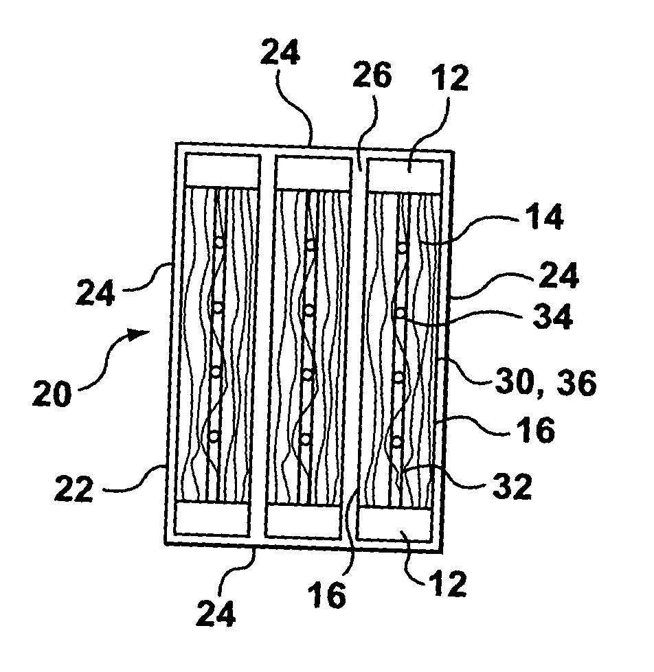
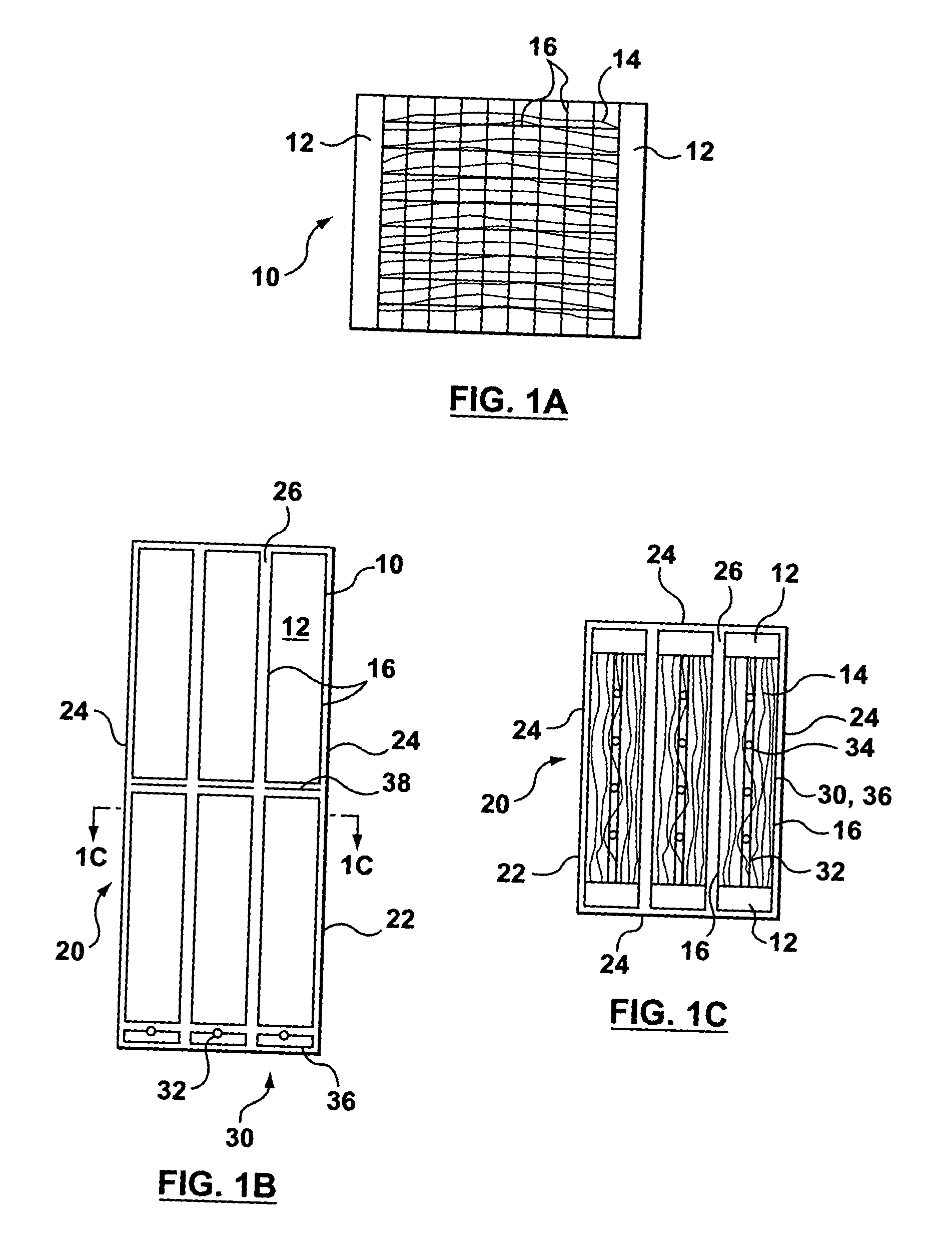
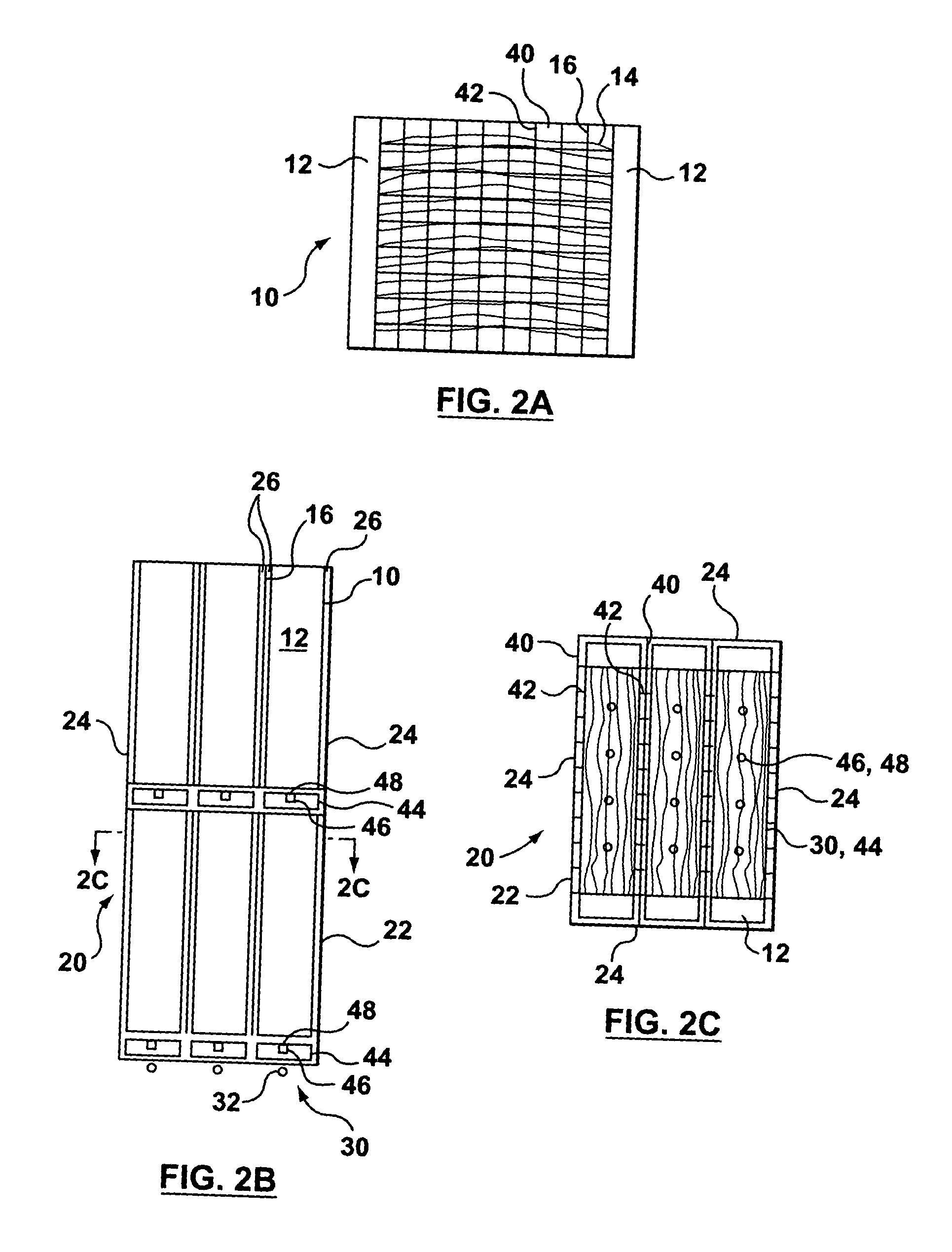
[0012] In the current invention, the three flows do not occupy the same space while flowing in the same direction. All three flows must pass through the membrane area but, where they do, they are primarily in mutually orthogonal directions. In particular, the permeate flows generally horizontally along the length of fiber membranes. Deconcentration flows of feed or tank water through the membrane area also have a significant horizontal component, but are generally perpendicular to the fibers, until they clear the membrane area. The flow of scouring bubbles is vertical through the membrane area. These flows are facilitated, according to one aspect of the invention, by providing groups of horizontally oriented hollow fiber membranes in areas, for example in horizontally compressed, vertically oriented generally rectangular fiber areas, separated by vertical deconcentration passages or gaps. The gaps provide a less resistive path for vertical
water flow than through the membrane area. An optional plate below or integrated with the aerator across the bottom of the fiber area may inhibit deconcentration flows from traveling vertically through the fiber area. Flow through shrouds or panels separate the fiber area from the gaps. However, the shrouds allow deconcentration flows to travel vertically through the passages, but horizontally, or partially horizontally, through the shrouds into or out of the fiber area. In this way, the effect of these flows on each other are reduced. In particular, the fibers can be packed uniformly across the entire fiber area. This, combined with a reduction in air lift effects through passages in the fiber area, encourages a more even distribution of scouring bubbles both horizontally and vertically and reduces unintended local high velocity flows of water by air lift during air scouring. Further, water velocities during deconcentration for a deep module or stack of modules can be reduced by a factor of 4 to 50, or to 1 cm / s or less. This reduces stress on the fibers and allows a wider range of fiber lengths, or strengths to be used. The average distance that solids travel through the fiber area during deconcentration is also reduced, for example to about 10 cm or less, regardless of the height of the module or stack of modules. Resistance to flow out of the tank during deconcentration is also reduced. Deconcentration may still be performed by overflow or tank draining.

