High voltage device with a particle trap

Active Publication Date: 2005-09-01
HITACHI ENERGY SWITZERLAND AG
View PDF4 Cites 1 Cited by
  • Summary
  • Abstract
  • Description
  • Claims
  • Application Information

AI Technical Summary

Benefits of technology

[0004] One object of the invention is therefore to provide a high-voltage switching device of the type mentioned initially which does not have the disadvantages mentioned above. One particular aim is to provide a high-voltage switching device which has high operational reliability.

Problems solved by technology

A high-voltage switching device such as this has the disadvantage that its dielectric strength and hence its operational reliability are not ensured well during operation.

Method used


Image

  • High voltage device with a particle trap
  • High voltage device with a particle trap
  • High voltage device with a particle trap

Examples


Embodiment Construction

[0004] One object of the invention is therefore to provide a high-voltage switching device of the type mentioned initially which does not have the disadvantages mentioned above. One particular aim is to provide a high-voltage switching device which has high operational reliability.

[0005] This object is achieved by an apparatus and a method having the features of the independent patent claims.

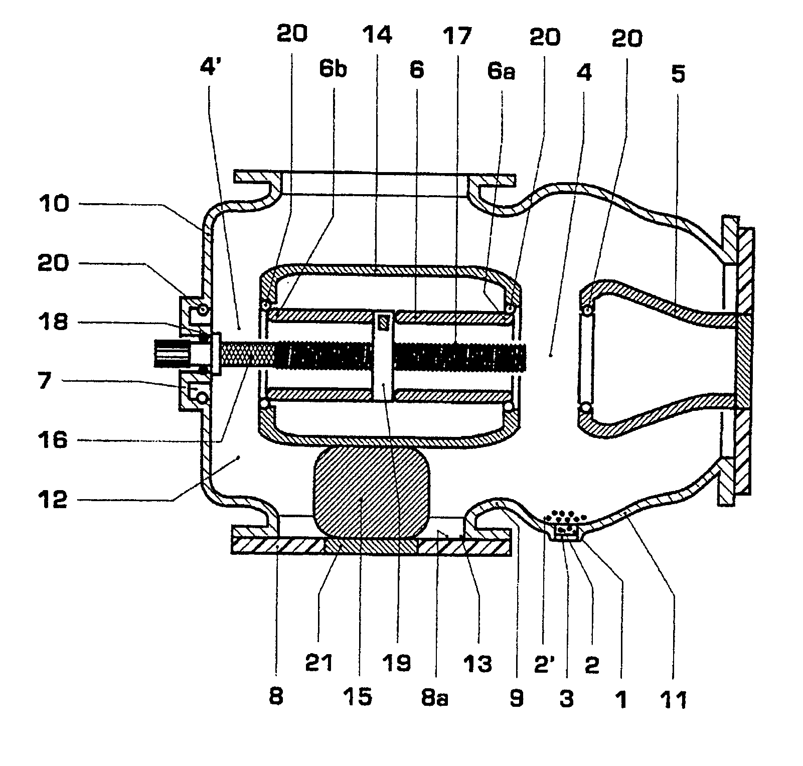
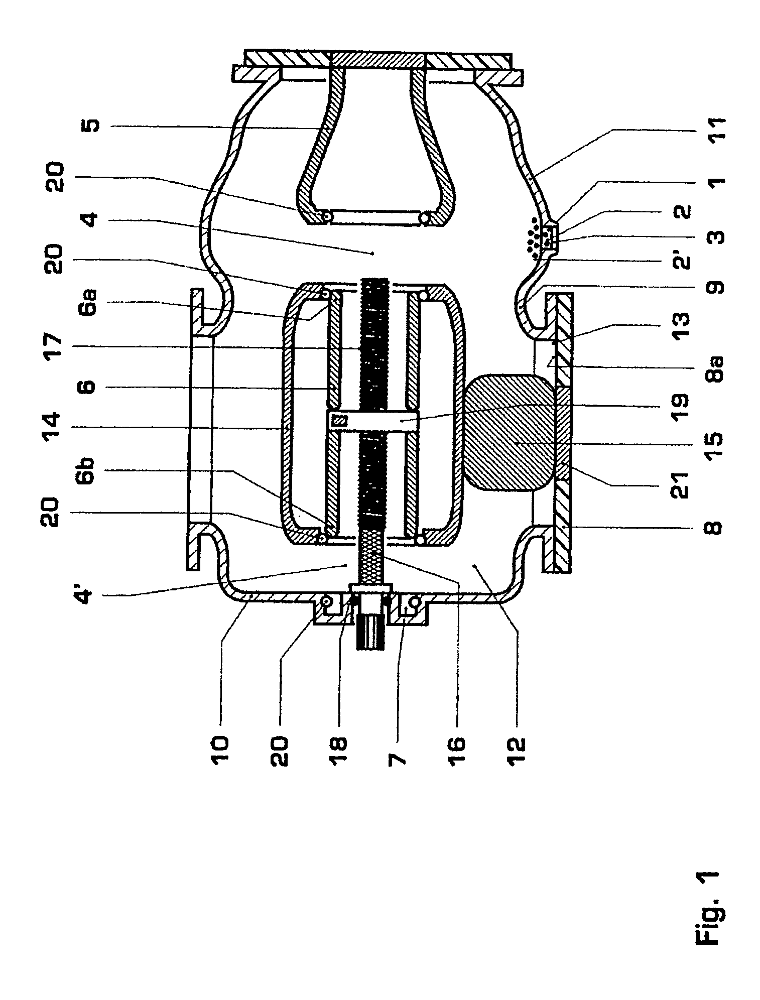
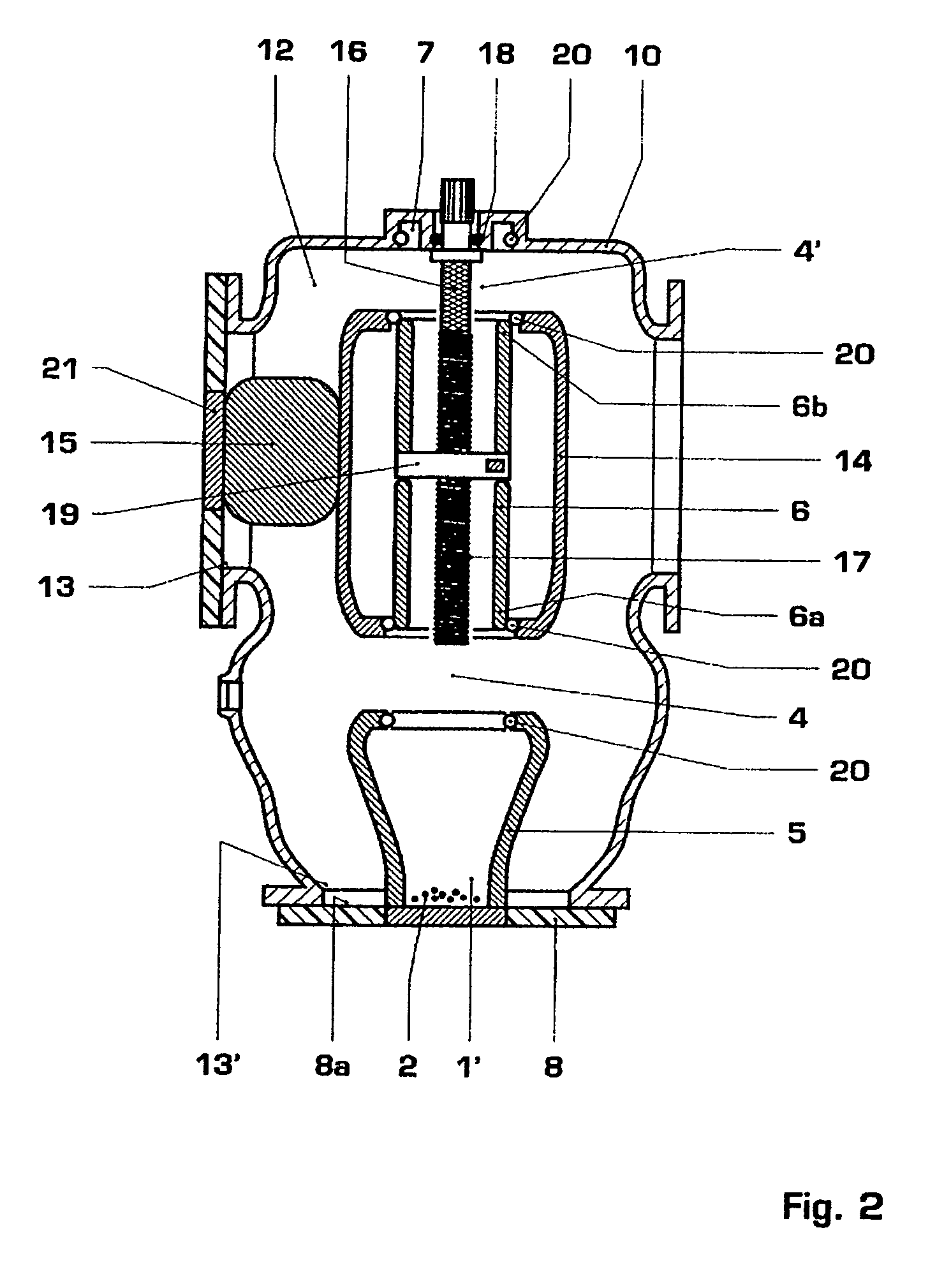
[0006] The high-voltage switching device according to the invention, which can be used in at least one installation position and has metallic encapsulation, containing a switching gap and a particle trap for holding foreign body particles, is characterized in that in the at least one installation position, the particle trap is arranged vertically underneath the switching gap, and in that, in the at least one installation position, an isolator part is provided, which has a surface that is aligned essentially horizontally and faces the interior of the high-voltage switching device, with a metall...


PUM


Abstract

The high-voltage switching device can be used in at least one installation position and has metallic encapsulation (10). It contains a switching gap (4) and a particle trap (1) for holding foreign body particles (2), and is characterized in that in the at least one installation position, the particle trap (1) is arranged vertically underneath the switching gap (4), and in that, in the at least one installation position, an isolator part (8) is provided, which has a surface (8a) that is aligned essentially horizontally and faces the interior of the high-voltage switching device, with a metallic wall (9), which is higher than the particle trap (1; 1′), being arranged between the isolator part (8) and the particle trap (1; 1′). The particle trap (1) preferably has a viewing window (3). If the high-voltage switching device is a disconnector, this viewing window (3) may be identical to the viewing window (3) for visual access to the visible disconnecting gap (4) of the disconnector. The high-voltage switching device can be used particularly advantageously in at least one second installation position and has a second particle trap, with the second particle trap being arranged vertically underneath the switching gap (4) in the at least one second installation position. This results in the high-voltage switching device having good operational reliability and a low susceptibility to defects.

Description

TECHNICAL FIELD [0001] The invention relates to the field of high-voltage switch technology. It relates to a high-voltage switching device and to a method for separation of foreign body particles in a high-voltage switching device as claimed in the precharacterizing clause of the independent claims, and to a high-voltage installation as claimed in claim 10. PRIOR ART [0002] A high-voltage switching device such as this is known, for example, from DE 41 20 309, which describes a particle trap which is in the form of a connecting stub that is closed by a cover and whose inside is provided with a protective coating. A particle trap such as this is intended for use in high-voltage switching devices which have grounded, metallic encapsulation enclosing a live active part. Foreign body particles which are located within the encapsulation and can reduce the dielectric strength of the high-voltage switching device are intended to be collected within the particle trap. The foreign body partic...

Claims


Application Information

Patent Timeline
IPC IPC(8): H01H33/24H02B13/055H01H33/56H02B13/02H02B13/045H02B13/065H02G1/00H02G5/00H02G5/06
CPCH01H33/245H01H2009/0292H01H33/56H02B1/04
Inventor HOLAUS, WALTERPAVLOVIC, BOJANGARCIA, MIGUELBLEIKER, DANIELSANCHEZ, DIEGO SOLOGUREN
Owner HITACHI ENERGY SWITZERLAND AG
Why Eureka
Try Eureka