Electrode holder

a technology of electrode holders and electrodes, applied in the direction of conductors, soldering devices, auxillary welding devices, etc., can solve the problems of extended work hours, limited binding force, and unsupportive heat for workers, and achieves the effect of prolonging work hours, suspending welding jobs, and reducing the binding for

Inactive Publication Date: 2005-09-01
KU JU CHING
View PDF3 Cites 87 Cited by
  • Summary
  • Abstract
  • Description
  • Claims
  • Application Information

AI Technical Summary

Benefits of technology

[0005] The primary purpose of the present invention is to provide an electrode holder that has at the bottom of a clamp of the handle provided with a fixation base to allow one end of an electrode lead to pass through; and the lead is fastened in place by a bolt in conjunction with a protection pad so that in the course of welding, the point of high temperature created by heat conduction is kept farthest from the hand gripping the holder to achieve working comfort.

Problems solved by technology

However, either way provides limited binding force as required and is applicable to the binding between two metal objects.
Such heat could become unbearable to the worker even wearing gloves and the work has to take a rest to wait for the temperature to cool down, thus suspended welding job and extended work hours.

Method used


Image

  • Electrode holder
  • Electrode holder
  • Electrode holder

Examples


Embodiment Construction

[0012] The following descriptions are of exemplary embodiments only, and are not intended to limit the scope, applicability or configuration of the invention in any way. Rather, the following description provides a convenient illustration for implementing exemplary embodiments of the invention. Various changes to the described embodiments may be made in the function and arrangement of the elements described without departing from the scope of the invention as set forth in the appended claims.

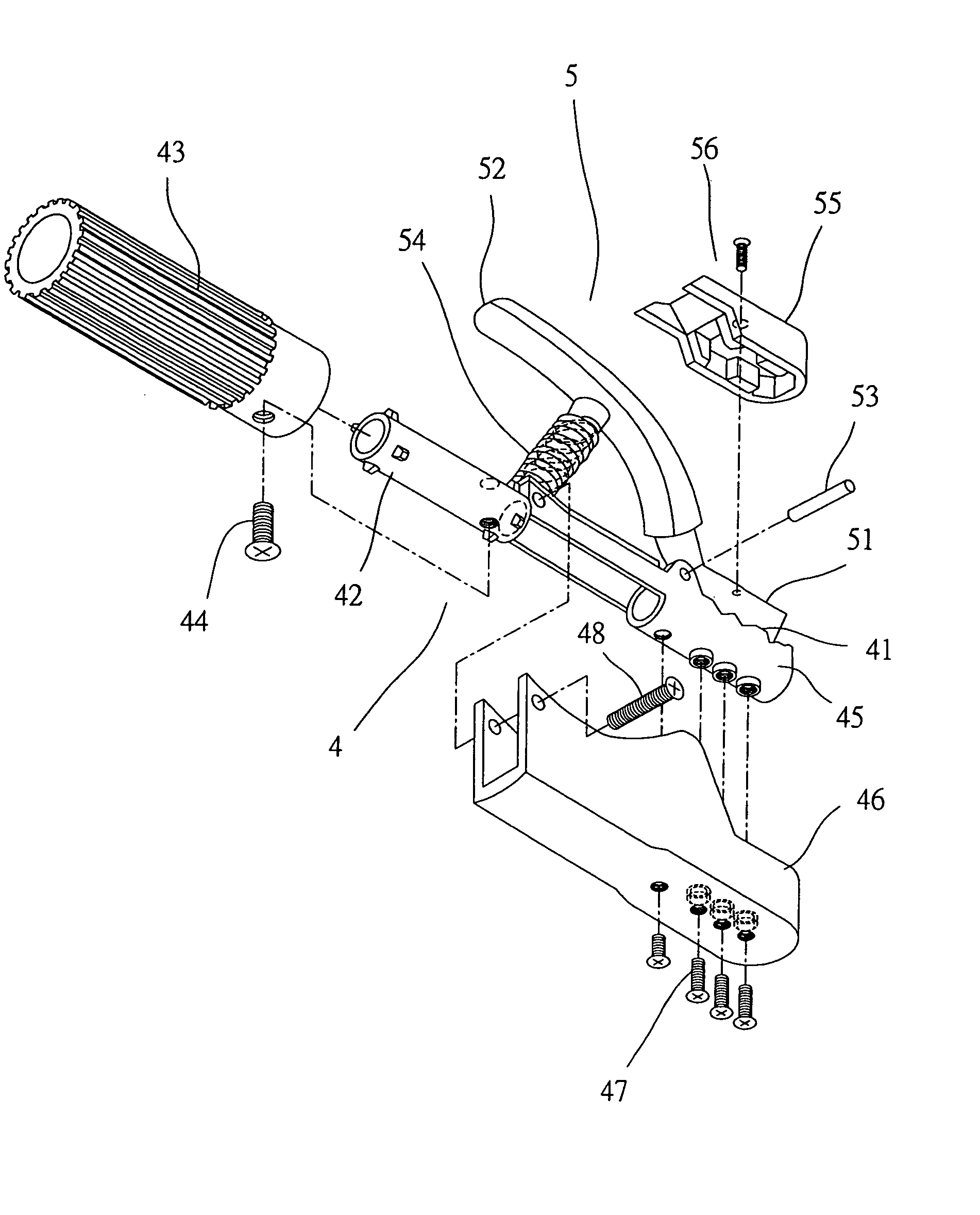
[0013] Referring to FIGS. 3 and 4, a preferred embodiment of the present invention related to an electrode holder is essentially comprised of a clamp 4 and a press 5. The clamp 4 includes a clamping section 41 at its front and a cylinder 42 at its rear. The clamping section 41 has an irregularly shaped upper edge. An electrode lead 6 penetrates through the cylinder 42 and the cylinder 42 is insulated with a grip 43. The proximate end of the grip 43 to the clamping section 41 is secured to the c...


PUM

PropertyMeasurementUnit
heat conductionaaaaaaaaaa
adhesionaaaaaaaaaa
binding forceaaaaaaaaaa

Abstract

An electrode holder comprised of a press and a clamp has at the bottom of the clamp adapted with a cylindrical base to allow one end of an electrode lead to pass through; the lead end being fastened in place by a bolt in conjunction with a protection pad covering up the cylindrical base so that in the course of welding, the point of heat conduction being kept farthest as from the hand gripping the holder to achieve working comfort.

Description

BACKGROUND OF THE INVENTION [0001] (a) Technical Field of the Invention [0002] The present invention is related to an electrode holder, and more particularly to one that improves work comforts by keeping the hand gripping the holder away from being affected by heat conduction. [0003] (b) Description of the Prior Art [0004] Economic growth drives the advancement made in industrial technology. In earlier time, the binding between two objects relied upon adhesion or tying. However, either way provides limited binding force as required and is applicable to the binding between two metal objects. Later, bolting and welding process was introduced. For the welding process, a welding machine and an electrode holder are used. Wherein, the electrode holder is connected to the welding machine by means of an electrode lead. A ground cable from the welding machine is connected to the work piece to be welded to become a loop while the electrode holder clamps an electrode rod. The electrode rod rel...

Claims


Application Information

Patent Timeline
Patent Type & Authority Applications(United States)
IPC IPC(8): B23K9/00B23K9/32B23K37/02
CPCB23K2201/38B23K9/32B23K2101/38
Inventor KU, JU-CHING
Owner KU JU CHING
Why Eureka
Try Eureka