Reflector antenna radome with backlobe suppressor ring and method of manufacturing

Active Publication Date: 2005-09-01
COMMSCOPE TECH LLC
View PDF19 Cites 61 Cited by
  • Summary
  • Abstract
  • Description
  • Claims
  • Application Information

AI Technical Summary

Problems solved by technology

Where significant backlobes are generated, signal interference with other RF systems may occur and overall antenna efficiency is reduced.
However, shield structures increase the overall size, wind load and thereby structural requirements of the antenna, increasing overall antenna and antenna support structure costs.
However, these structures, in addition to significantly increasing the manufacturing costs of the resulting antenna, increase antenna

Method used


Image

  • Reflector antenna radome with backlobe suppressor ring and method of manufacturing
  • Reflector antenna radome with backlobe suppressor ring and method of manufacturing
  • Reflector antenna radome with backlobe suppressor ring and method of manufacturing

Examples


Embodiment Construction

[0015] The invention is described in an exemplary embodiment applied upon a radome also having toolless quick attach / detach features further described in U.S. utility patent application Ser. No. 10 / 604,756 “Dual Radius Twist Lock Radome and Reflector Antenna for Radome”, by Junaid Syed et al, filed Aug. 14, 2003 and hereby incorporated by reference in the entirety. The invention is described herein with respect to a single profile radome. One skilled in the art will appreciate that the invention may also be applied, for example, to the dual radius radome configurations disclosed in the aforementioned application.

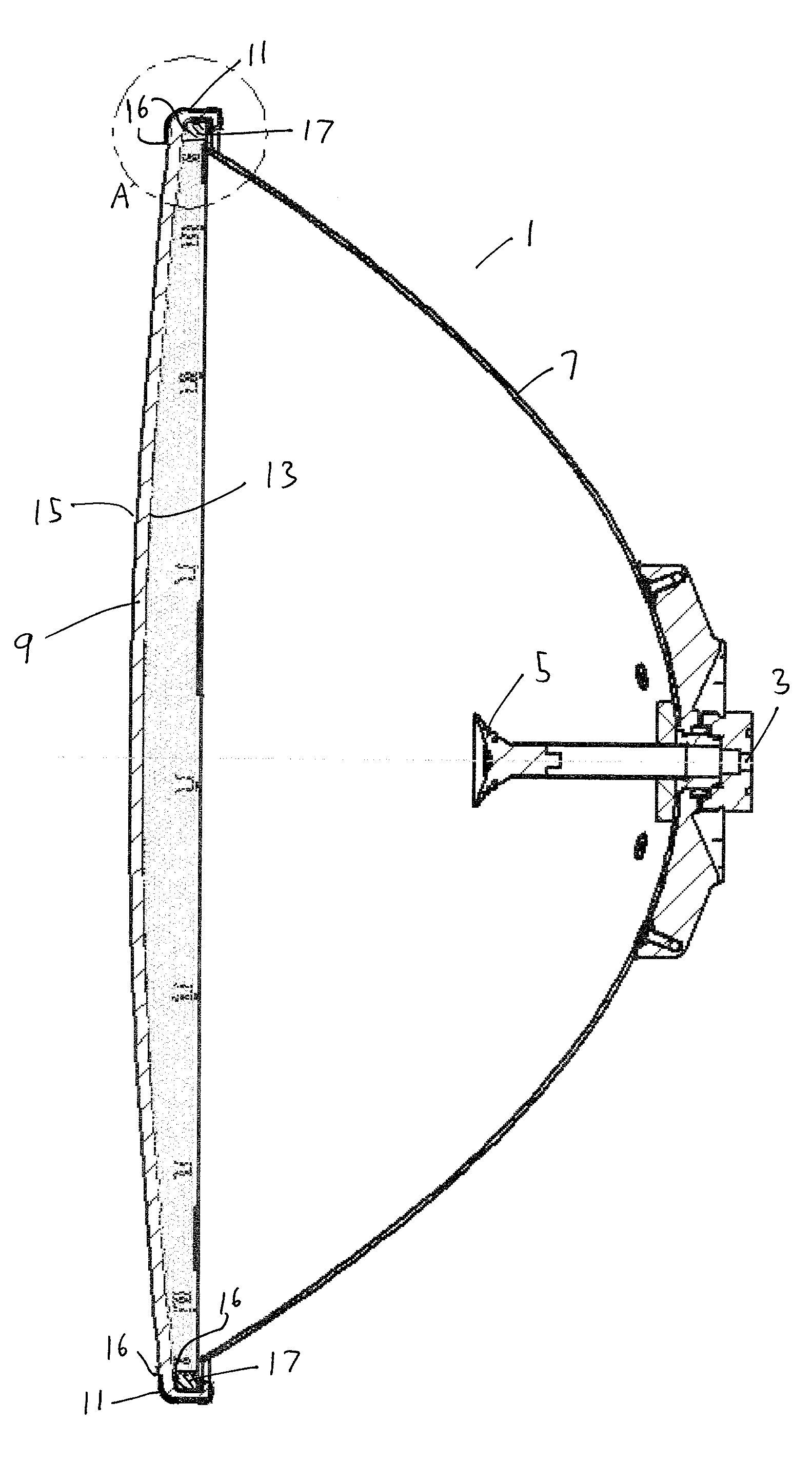
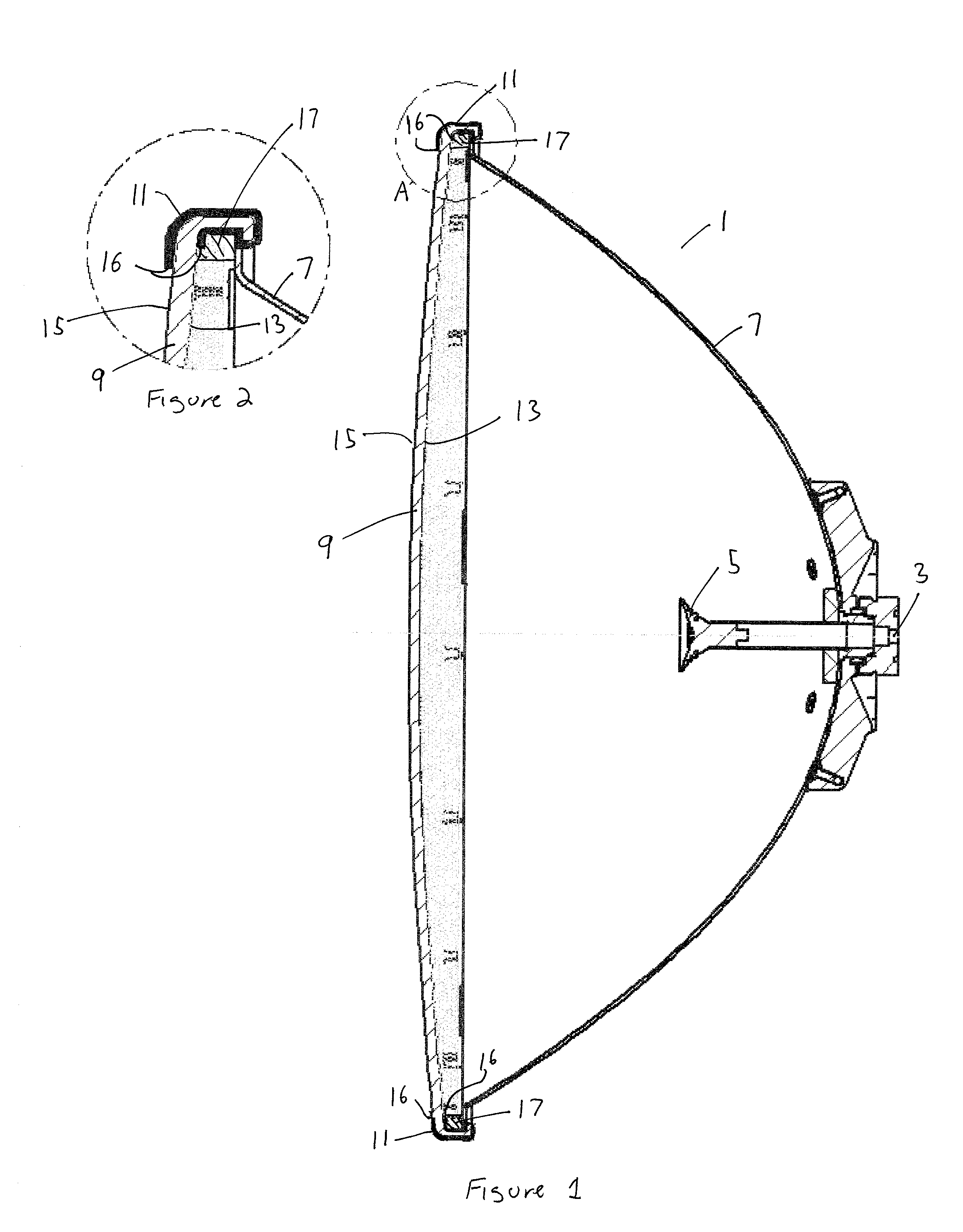
[0016] As shown in FIG. 1, a typical deep dish reflector antenna 1 projects a signal from a feed 3 upon a sub reflector 5 which reflects the signal to illuminate the reflector 7. A radome 9 covers the open distal end of the reflector 7 to form an environmental seal and reduce the overall wind load of the antenna 1.

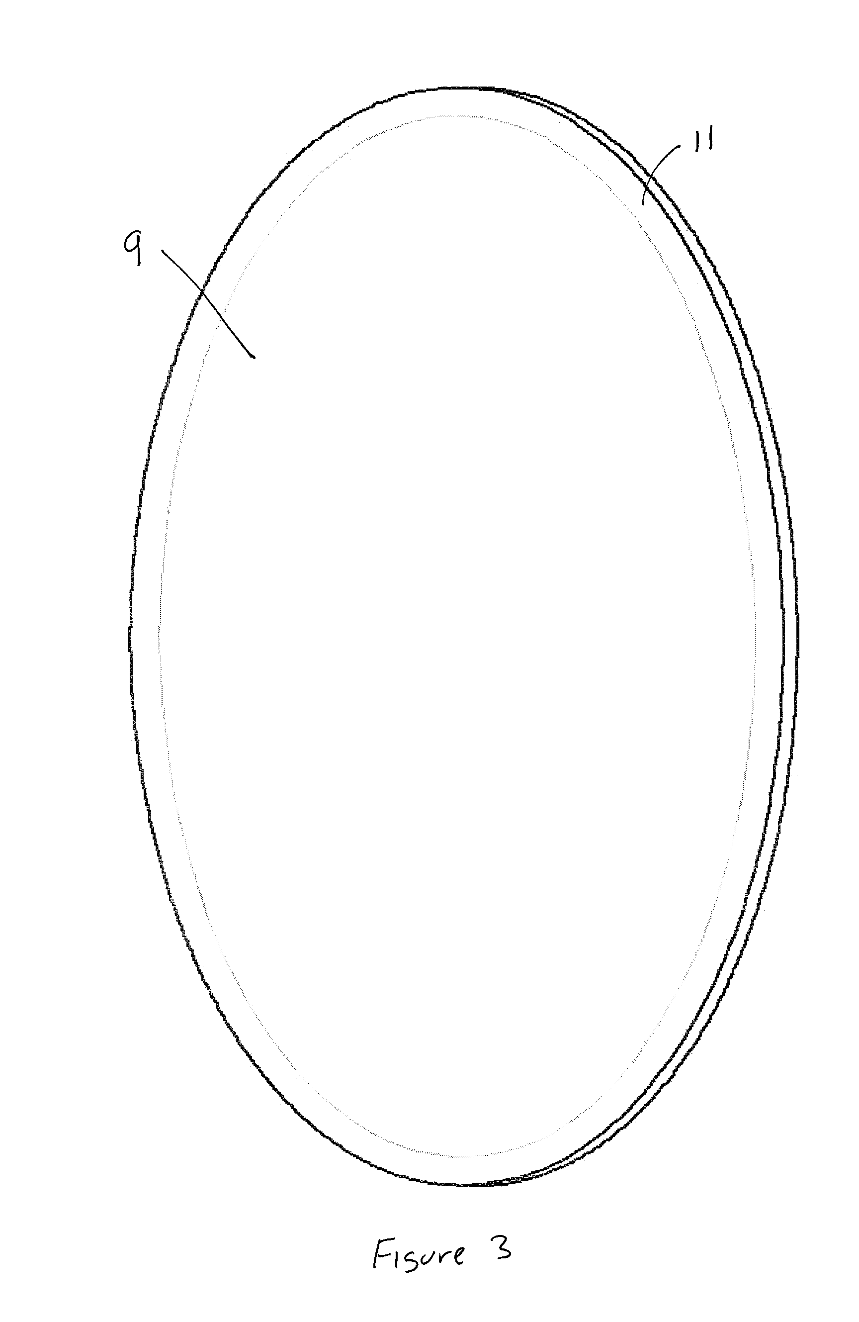
[0017] As shown in FIGS. 2 and 3, a conductive ring herein ...


PUM


Abstract

A radome adapted to reduce backlobes of an associated reflector antenna via application of a conductive ring with an inward facing edge about the periphery of the radome. The conductive ring may be applied extending around the radome periphery to an inside and or outside surface of the radome. The conductive ring may be formed upon the radome by metalising, electrodaging, over molding or the like. Further, the conductive ring may be a metal, metallic foil, conductive foam or the like which is coupled to the radome. An absorber in the form of a ring or a surface coating applied to the radome and or the distal end of the reflector may also be added between the radome and the reflector.

Description

BACKGROUND OF INVENTION [0001] 1. Field of the Invention [0002] This invention relates to reflector antenna radomes. More particularly, the invention relates to a reflector antenna radome with a backlobe suppression ring around the radome periphery. [0003] 2. Description of Related Art [0004] The front to back (F / B) ratio of a reflector antenna indicates the proportion of the maximum antenna signal that is radiated in any backward directions relative to the main beam, across the operating band. Rearward signal patterns, also known as backlobes, are generated by edge diffraction occurring at the periphery of the reflector dish. Where significant backlobes are generated, signal interference with other RF systems may occur and overall antenna efficiency is reduced. Local and international standards groups have defined acceptable F / B ratios for various RF operating frequency bands. [0005] Prior reflector antennas have used a range of different solutions to maintain an acceptable F / B rat...

Claims


Application Information

Patent Timeline
IPC IPC(8): H01Q1/42H01Q19/02H01Q19/19
CPCH01Q19/19H01Q19/022
Inventor SYED, JUNAIDCAMPBELL, ROYSUTHERLAND, DAVID
Owner COMMSCOPE TECH LLC
Why Eureka
Try Eureka