Method of driving an ink-jet printhead

a technology of inkjet printing and inkjet printing, which is applied in printing, specific water treatment objectives, transportation and packaging, etc., can solve the problems of deteriorating print quality, difficult ejection timing control of two droplets, and inability to accurately adjust the retreat timing of the meniscus of ink, so as to reduce the change in the ejection speed of droplets

Inactive Publication Date: 2005-09-01
SAMSUNG ELECTRO MECHANICS CO LTD
View PDF8 Cites 40 Cited by
  • Summary
  • Abstract
  • Description
  • Claims
  • Application Information

AI Technical Summary

Benefits of technology

[0018] It is a feature of an embodiment of the present invention to provide a method of driving an ink-jet printhead that is capable of adjusting a volume of an ejected ink droplet for the representation of gradation while reducing a change in an ejection speed of the droplet.
[001

Problems solved by technology

However, in the above driving method, accurately adjusting a timing of the retreat of the meniscus of the ink is difficult.
Accordingly, a position of the dot on the recording medium is changed, which deteriorates print quality.
However, in the above conventional driving method, ejection timing control is difficult with

Method used


Image

  • Method of driving an ink-jet printhead
  • Method of driving an ink-jet printhead
  • Method of driving an ink-jet printhead

Examples


first embodiment

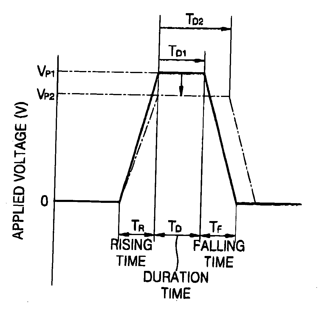
[0039] Referring to FIG. 4, in a method of driving an ink-jet printhead according to the present invention, a driving pulse applied to a piezoelectric actuator for ejecting an ink droplet is a trapezoidal waveform. An overall time of the driving pulse having the trapezoidal waveform consists of a rising time TR, during which time a voltage increases, a duration time TD, during which time the maximum voltage VP, i.e., a driving voltage, is constantly maintained, and a falling time TF, during which time the voltage decreases.

[0040] In the first embodiment of the present invention, by maintaining the rising time TR of the driving pulse constant and adjusting the duration time TD of the maximum voltage VP, a volume of a droplet ejected through a nozzle may be adjusted. Accordingly, the volume of the droplet ejected through the nozzle can be varied according to the adjustment of the duration time TD of the maximum voltage VP. Simultaneously, an ejection speed of the droplet may be mainta...

second embodiment

[0055]FIG. 8 illustrates waveforms of a driving pulse used in a method of driving an ink-jet printhead according to the present invention. FIG. 9 illustrates a cross-sectional view explaining that, although a driving frequency increases, the volume of the ink droplet is constantly maintained in the method of FIG. 8.

[0056] Referring to FIG. 8, in the second embodiment of the present invention, when the rising time TR of the driving pulse applied to the piezoelectric actuator is constantly maintained, the duration time TD of the maximum voltage VP and the maximum voltage VP may be adjusted together. Then, not only may the volume of the droplet be varied while the ejection speed of the droplet is maintained relatively constant, but also the volume of the droplet in the high frequency range does not decrease as compared to that in the low frequency range due to the adjustment of the maximum voltage VP.

[0057] More specifically, when the driving frequency is relatively high, e.g., ten (1...


PUM


Abstract

A method of driving an ink-jet printhead, the ink-jet printhead having a pressure chamber to be filled with ink, a piezoelectric actuator for varying a volume of the pressure chamber, and a nozzle, through which an ink droplet is ejected, connected to the pressure chamber, the method including applying a driving pulse to the piezoelectric actuator to change the volume of the pressure chamber, thereby ejecting the ink droplet through the nozzle due to a change in pressure in the pressure chamber caused by the change in volume of the pressure chamber, and changing a volume of the ink droplet ejected through the nozzle by maintaining a rising time of the driving pulse constant and adjusting a duration time of a maximum voltage of the driving pulse.

Description

BACKGROUND OF THE INVENTION [0001] 1. Field of the Invention [0002] The present invention relates to a method of driving an ink-jet printhead. More particularly, the present invention relates to a method of driving an ink-jet printhead using a driving waveform capable of representing gradation. [0003] 2. Description of the Related Art [0004] In general, ink-jet printheads eject fine droplets of ink for printing at desired positions on a recording medium to print an image of a predetermined color. Ink-jet printheads may be classified into two types according to a mechanism used to eject an ink droplet. A first type is a bubble jet type ink-jet printhead, which generates a bubble in ink using a heat source to eject an ink droplet by an expansion force of the bubble. A second type is a piezoelectric type ink-jet printhead, which ejects an ink droplet by pressure applied to ink due to a deformation of a piezoelectric body. [0005]FIG. 1 illustrates a structure of a conventional piezoelec...

Claims


Application Information

Patent Timeline
IPC IPC(8): B41J2/045B41J2/055B41J2/205B41J29/38
CPCB41J2/04581B41J2/04588B41J2/04593B41J2/04591B41J2/0459C02F1/50C02F2303/04B01F35/2214B01F35/892B01F2101/48
Inventor LIM, SEONG-TAEKCHUNG, JAE-WOOKIM, JONG-BEOMLEE, KWANG-HO
Owner SAMSUNG ELECTRO MECHANICS CO LTD
Why Eureka
Try Eureka