
Interworking between Ethernet and non-Ethernet customer sites for VPLS

Inactive Publication Date: 2005-09-01
CISCO TECH INC
View PDF25 Cites 138 Cited by
  • Summary
  • Abstract
  • Description
  • Claims
  • Application Information

AI Technical Summary

Problems solved by technology

The difficulty with this approach is that many service providers are reluctant to adopt such configurations because their customer's CE devices either do not have such capability, or cannot easily be configured for such operation.
The drawback of this solution, however, is that it fails to address the desire of those service providers who wish to maintain the service offering to their customers at Layer 2; that is, service providers who want to offer VPLS service to their customers.
This solution is also unacceptable to those customers who want to retain the ability to manage their data packet routes.
In other words, although MPLS Layer 3 VPNs provide “any-to-any” connectivity, some enterprises are reluctant to relinquish routing control of their network and desire L2VPN services with multipoint connectivity.

Method used


Image

  • Interworking between Ethernet and non-Ethernet customer sites for VPLS
  • Interworking between Ethernet and non-Ethernet customer sites for VPLS
  • Interworking between Ethernet and non-Ethernet customer sites for VPLS

Examples


Embodiment Construction

[0018] A method and apparatus for providing VPLS service with interworking among a customer's heterogeneous sites (i.e., sites with Ethernet and non-Ethernet interfaces) without the need for configuration changes in the customer's CEs is described. In the following description specific details are set forth, such as device types, protocols, configurations, etc., in order to provide a thorough understanding of the present invention. However, persons having ordinary skill in the networking arts will appreciate that these specific details may not be needed to practice the present invention.

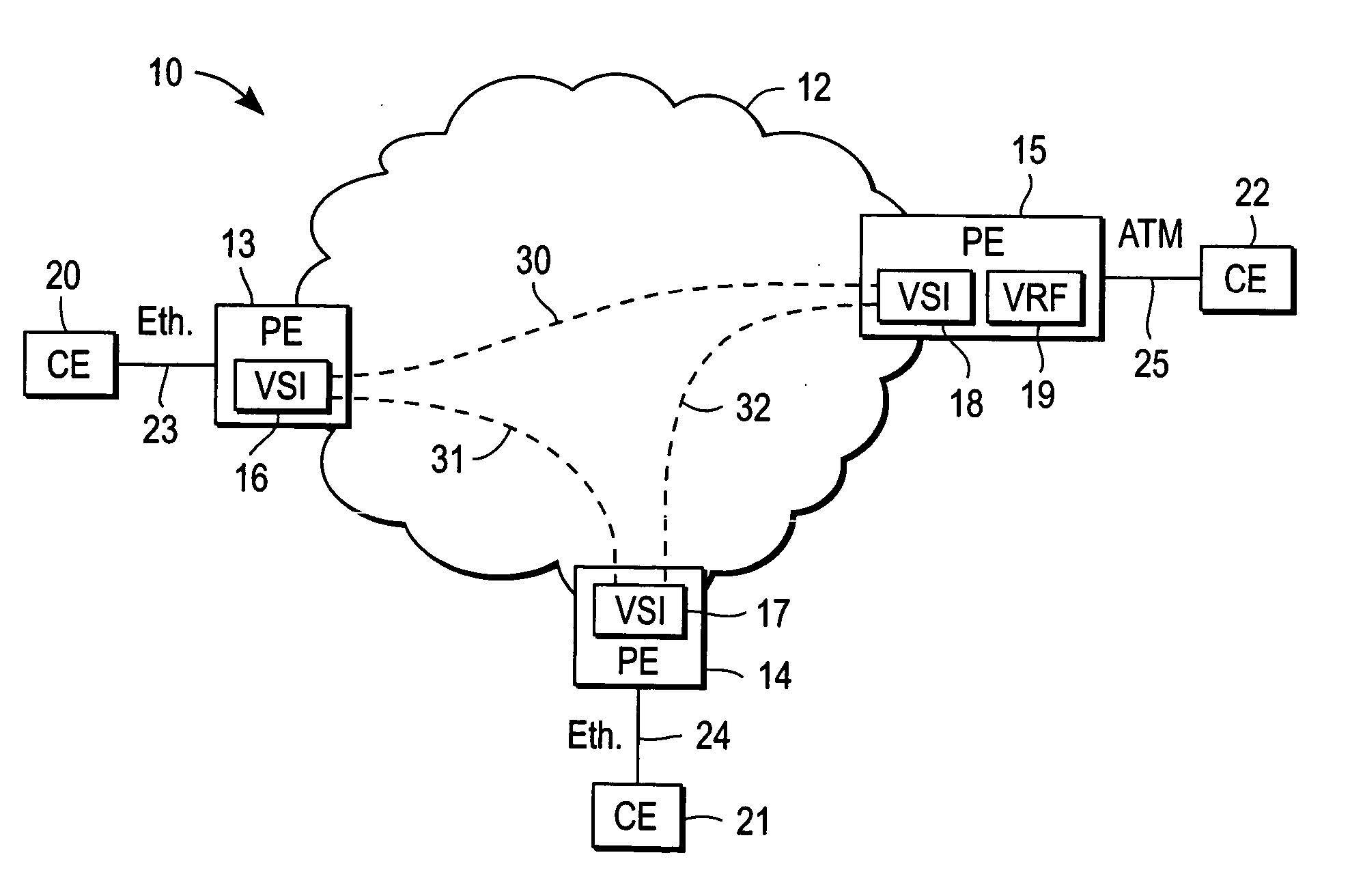
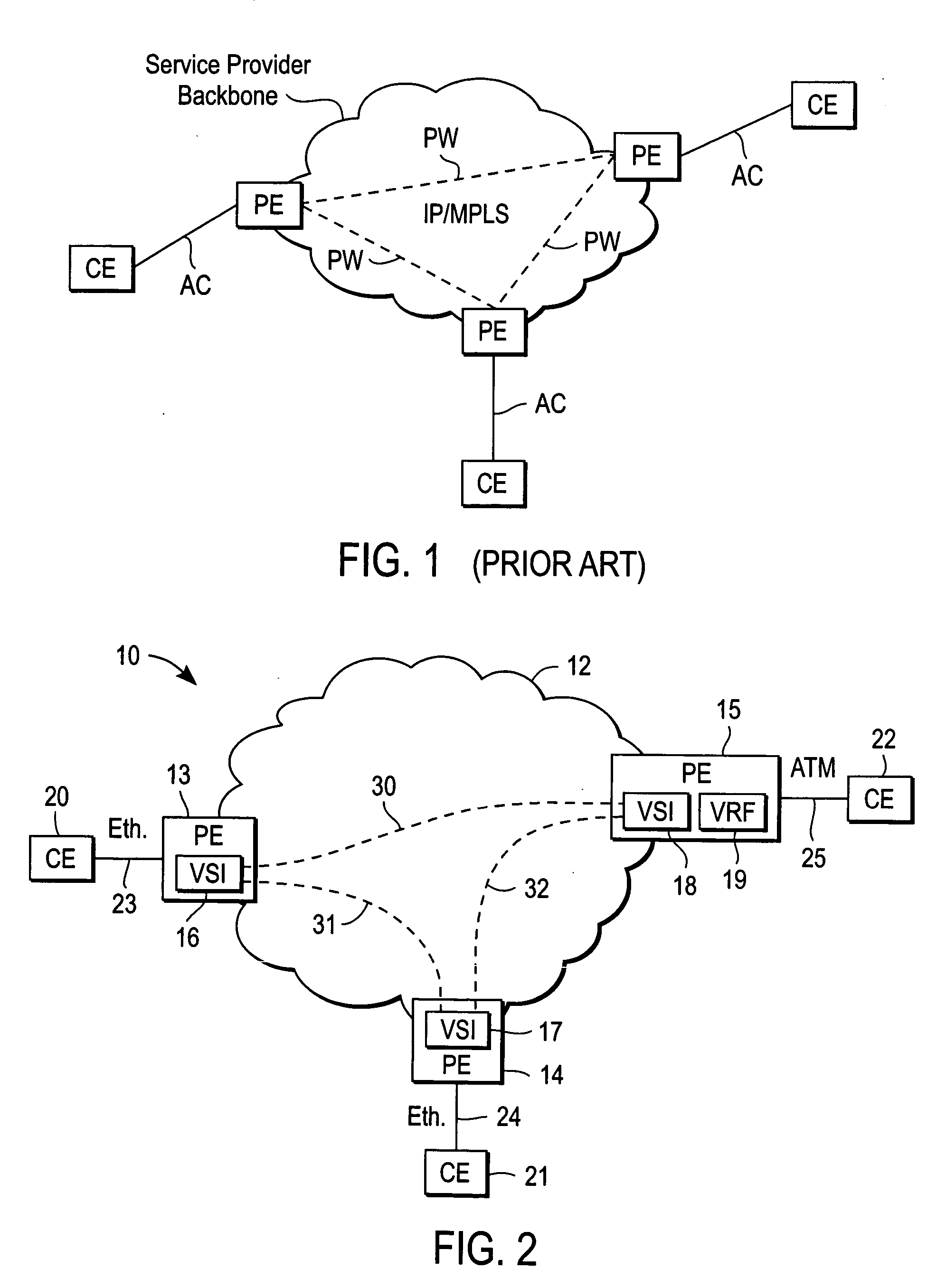
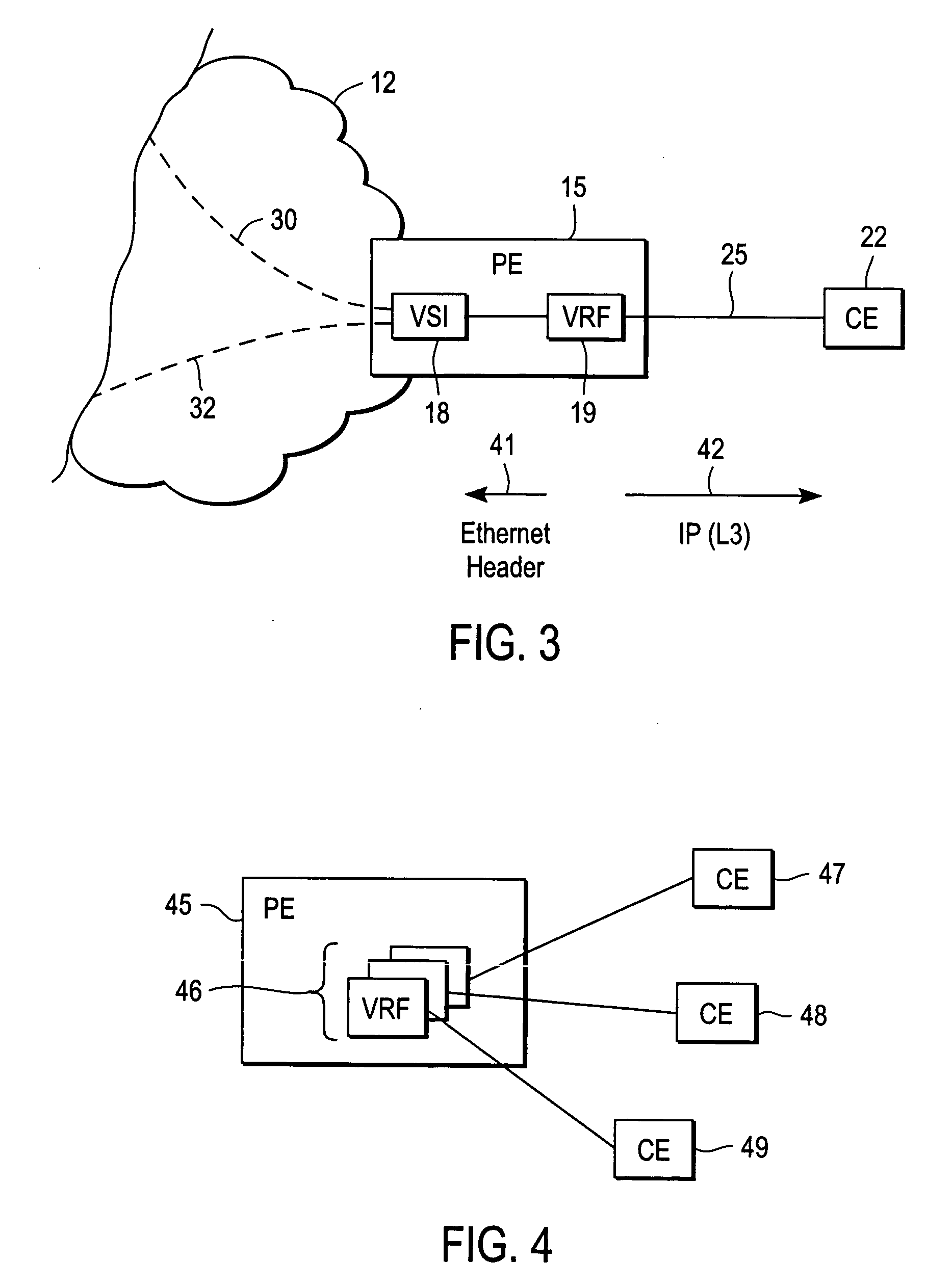
[0019]FIG. 2 illustrates an exemplary system 10 providing VPLS service to a customer having three sites / CEs in accordance with one embodiment of the present invention. A Service Provider (SP) network infrastructure 12 includes three Provider Edge devices 13-15, which are shown coupled to three customer sites / CEs 20-22 via ACs 23-25, respectively. CE 20 and 21 each have Ethernet interfaces, whereas S...


PUM


Abstract

A method and apparatus for interworking between customer edge (CE) devices connected to provider edge (PE) devices via attachment circuits (ACs), the PE devices routing packets across a service provider (SP) network, the CE devices including one or more Ethernet CE devices and a non-Ethernet CE. A virtual switch instance (VSI) is provided on a first PE device coupled to the non-Ethernet CE. The first PE device also including a virtual routing forwarding (VRF) entity interfaced with the VSI such that the SP network appears to offer L3VPN service toward the non-Ethernet CE and VPLS toward the one or more Ethernet CE devices. It is emphasized that this abstract is provided to comply with the rules requiring an abstract that will allow a searcher or other reader to quickly ascertain the subject matter of the technical disclosure. It is submitted with the understanding that it will not be used to interpret or limit the scope or meaning of the claims. 37 CFR 1.72(b).

Description

FIELD OF THE INVENTION [0001] The present invention relates generally to digital computer network technology; more particularly, to methods and apparatus for providing metro Ethernet services. BACKGROUND OF THE INVENTION [0002] Many enterprises are changing their business processes using advanced information technology (IT) applications to achieve enhanced productivity and operational efficiencies. These advanced applications tend to place increasing importance on peer-to-peer data communications, as compared to traditional client-server data communications. As a result, the underlying network architecture to support these applications is evolving to better accommodate this new model. [0003] The performance of many peer-to-peer applications benefit from being implemented over service provider networks that support multipoint network services. A multipoint network service is one that allows each customer edge (CE) end point or node to communicate directly and independently with all o...

Claims


Application Information

Patent Timeline
IPC IPC(8): H04L12/28H04L12/46H04L12/56
CPCH04L12/2856H04L12/2881H04L45/586H04L45/507H04L45/00
Inventor SAJASSI, ALI
Owner CISCO TECH INC
Learn More