
Stress measurement method using X-ray diffraction

a stress measurement and x-ray diffraction technology, applied in the direction of force measurement by measuring optical property variation, material analysis using wave/particle radiation, instruments, etc., can solve the problem of no stress measurement method more precise than the conventional sinsup>2/sup> method, and achieve the effect of precise stress measuremen

Inactive Publication Date: 2005-09-01
RIGAKU CORP
View PDF14 Cites 7 Cited by
  • Summary
  • Abstract
  • Description
  • Claims
  • Application Information

AI Technical Summary

Benefits of technology

The present invention provides a more precise method for measuring the stress of a c-axis-oriented specimen of a tetragonal polycrystal compared to the conventional sin2ψ method. The method involves preparing a specimen, defining a coordinate system, irradiating the specimen with X-rays, detecting the diffracted X-rays, adjusting the X-ray optical system to find the diffraction angle at which the X-rays exhibit a maximum intensity, and determining the strain based on the diffraction angle measured in the non-strain state. The method can also be used to measure the strain under an equi-biaxial stress state. The invention provides a more accurate measurement of stress in tetragonal polycrystals, which is useful in various fields such as materials science and engineering.

Problems solved by technology

However, with respect to a fiber texture specimen of a tetragonal polycrystal (in this case, the c-axis of the tetragonal system is perpendicular to the specimen surface, the specimen being a c-axis-oriented specimen), no stress measurement method more precise than the conventional sin2ψ method has been developed.

Method used


Image

  • Stress measurement method using X-ray diffraction
  • Stress measurement method using X-ray diffraction
  • Stress measurement method using X-ray diffraction

Examples


Embodiment Construction

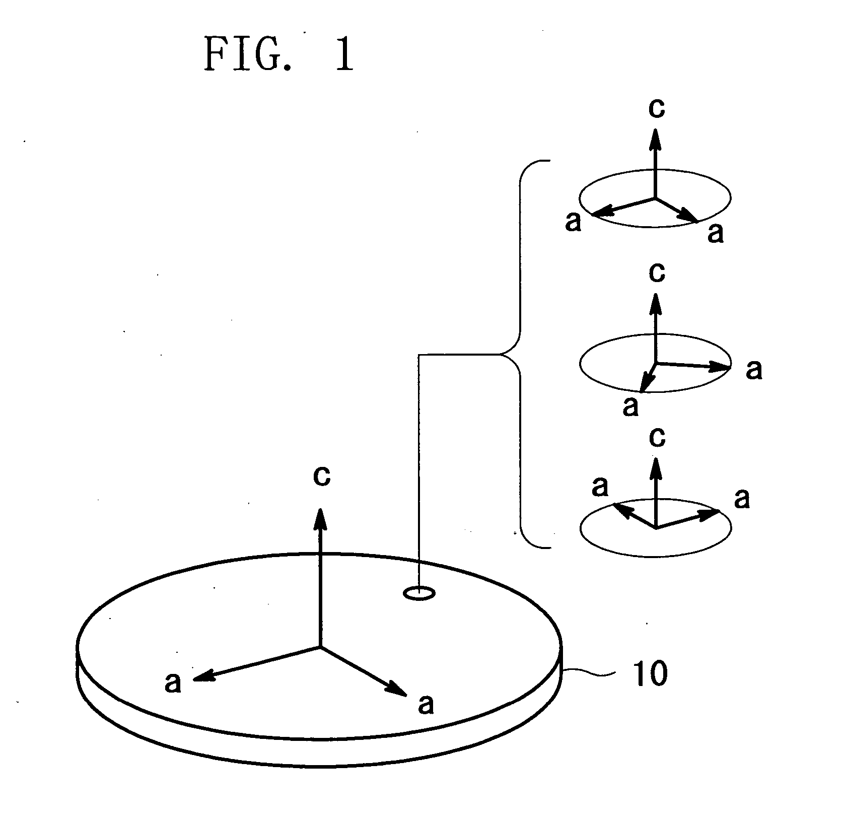
[0032] Referring to FIG. 1 illustrating a c-axis-oriented specimen of a tetragonal polycrystal, most of many crystal grains which are present in the vicinity of the surface of a specimen 10 have the c-axes of the tetragonal system perpendicular to the specimen surface. The remaining two axes (since these are equivalent to each other, both axes are referred to as a-axes) of the crystal axes of the tetragonal system are present within a plane parallel to the specimen surface. With respect to the c-axis-oriented specimen, in general, directions of the two a-axes are random, and randomly oriented crystal grains are mixed with each other. Such a c-axis-oriented specimen is the target for measurement of the present invention.

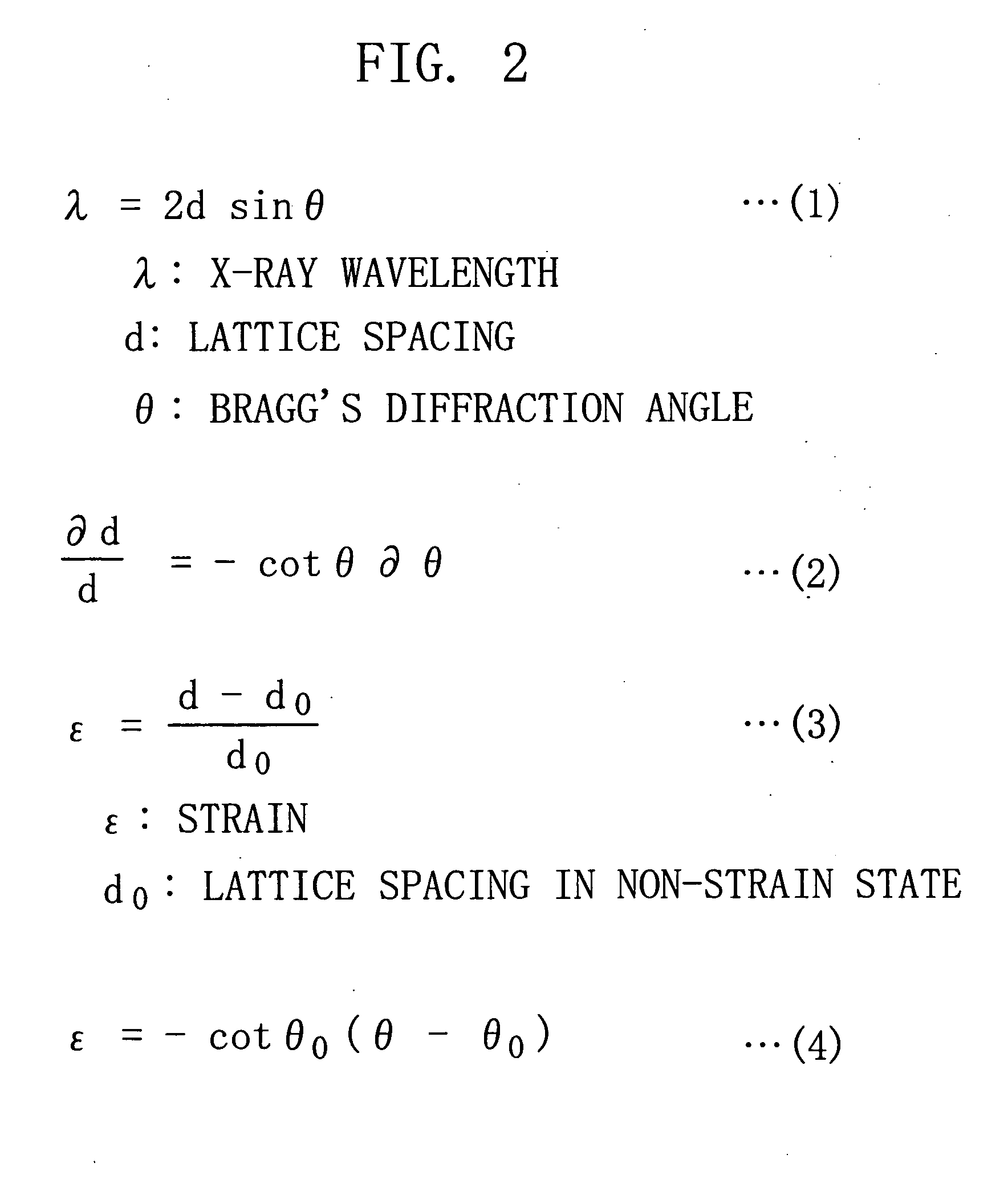
[0033] The principle of the stress measurement using X-ray diffraction will be briefly described with reference to the formulae shown in FIG. 2. Formula (1) is the Bragg's equation representing the diffraction condition of X-ray. Under the assumption that the wavelen...


PUM

PropertyMeasurementUnit
angleaaaaaaaaaa
lattice constantaaaaaaaaaa
stressaaaaaaaaaa

Abstract

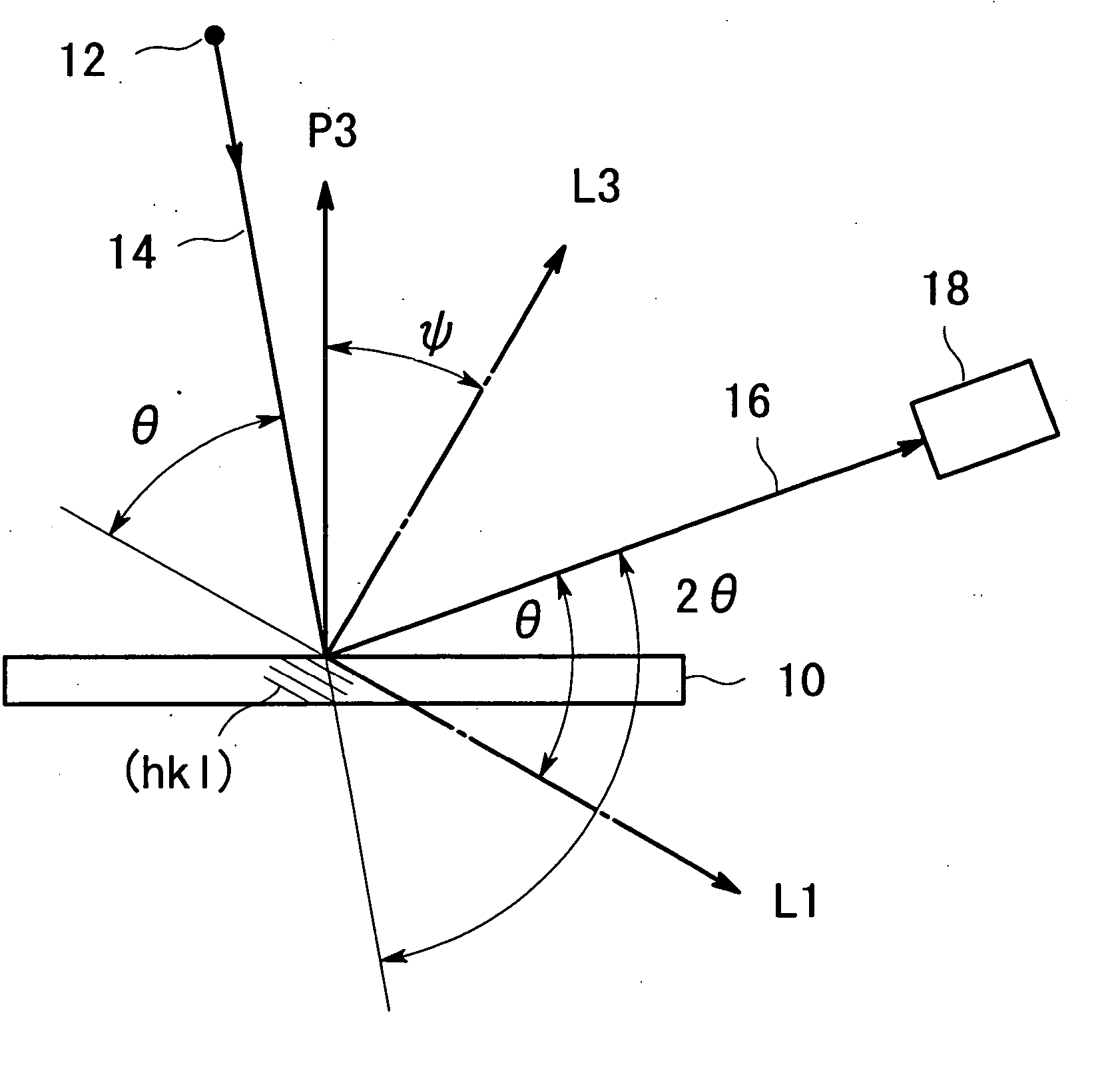
A stress of a c-axis-oriented specimen of a tetragonal polycrystal is measured using. X-ray diffraction under the assumption of a plane stress state. An X-ray optical system is set in the location of φ=0°, 45° or 90°. An X-ray diffracted at a crystal plane (the direction of the normal thereto is the direction of an angle of ψ) with the Miller indices (hkl) is detected. A diffraction angle θ in a strain state is measured in the vicinity of a Bragg's angle θ0 in a non-strain state. Strains ε with respect to a plurality of ψ are calculated from the difference between the measurement values θ and the Bragg's angle θ0. Specific stress calculation formulae are determined with respect to the tetragonal system having the Laue symmetry 4 / mmm. The stress is calculated from the slope of the linear line of plotted measurement results.

Description

[0001] The present application is a Continuation Application of U.S. application Ser. No. 10 / 650,059 filed Aug. 27, 2003.BACKGROUND OF THE INVENTION [0002] 1. Field of the Invention [0003] The present invention relates to a stress measurement method using X-ray diffraction. In particular, the present invention relates to a stress measurement method for a c-axis-oriented specimen of a tetragonal polycrystal. [0004] 2. Description of the Related Art [0005] In general, a sin2 ψ method has been used wish for the stress measurement method using X-ray diffraction. The sin2ψ method requires four conditions: (1) the crystal grain is small, (2) there is no strong preferred orientation, (3) a plane stress state is established within the depth of penetration of the X-ray, and (4) no stress gradient is present in the depth direction. [0006] The stress measurement of a polycrystalline specimen, in which a specific crystal axis orients in a specific direction (such an orientation is referred to a...

Claims


Application Information

Patent Timeline
Patent Type & Authority Applications(United States)
IPC IPC(8): G01L1/00G01B15/06G01L1/25G01N23/20G01N23/207H01L21/316
CPCH01L21/31691G01N23/207H01L21/02197
Inventor YOKOYAMA, RYOUICHIENDO, KAMIHISA
Owner RIGAKU CORP
Learn More