Motor assemblies and massage assemblies using the same

a technology of motor assemblies and massage devices, applied in the field of electric motor assemblies, can solve the problems of many of the massage devices that are currently on the market suffering from being too noisy and offering too little vibratory power, and achieve the effects of less noise, less noise, and increased vibratory power

a technology of motor assemblies and massage devices, applied in the field of electric motor assemblies, can solve the problems of many of the massage devices that are currently on the market suffering from being too noisy and offering too little vibratory power, and achieve the effects of less noise, less noise, and increased vibratory power

US20050192519A1Inactive Publication Date: 2005-09-01SIGMA INSTR

Image

  • Motor assemblies and massage assemblies using the same
  • Motor assemblies and massage assemblies using the same
  • Motor assemblies and massage assemblies using the same

Examples


Embodiment Construction

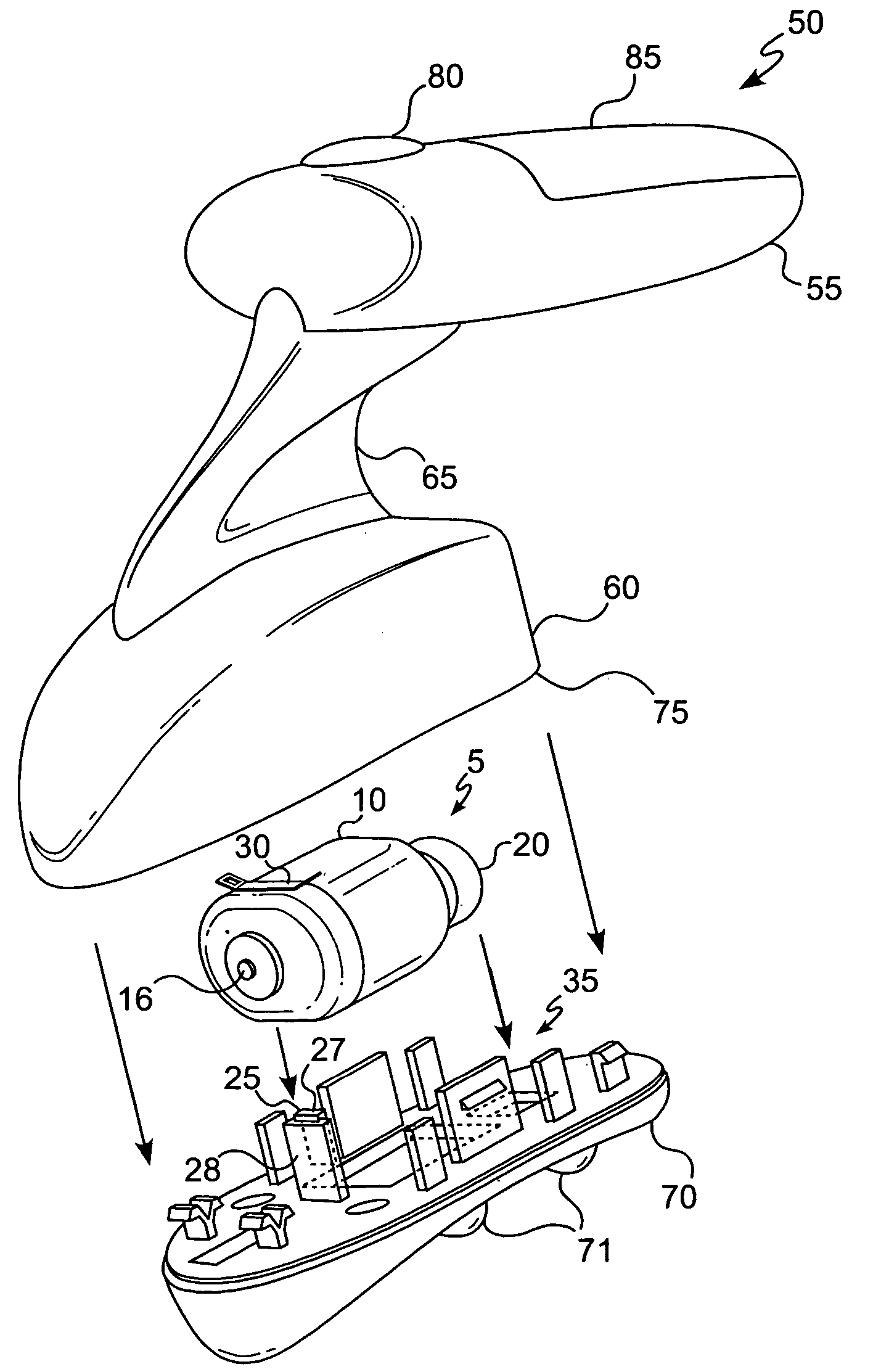
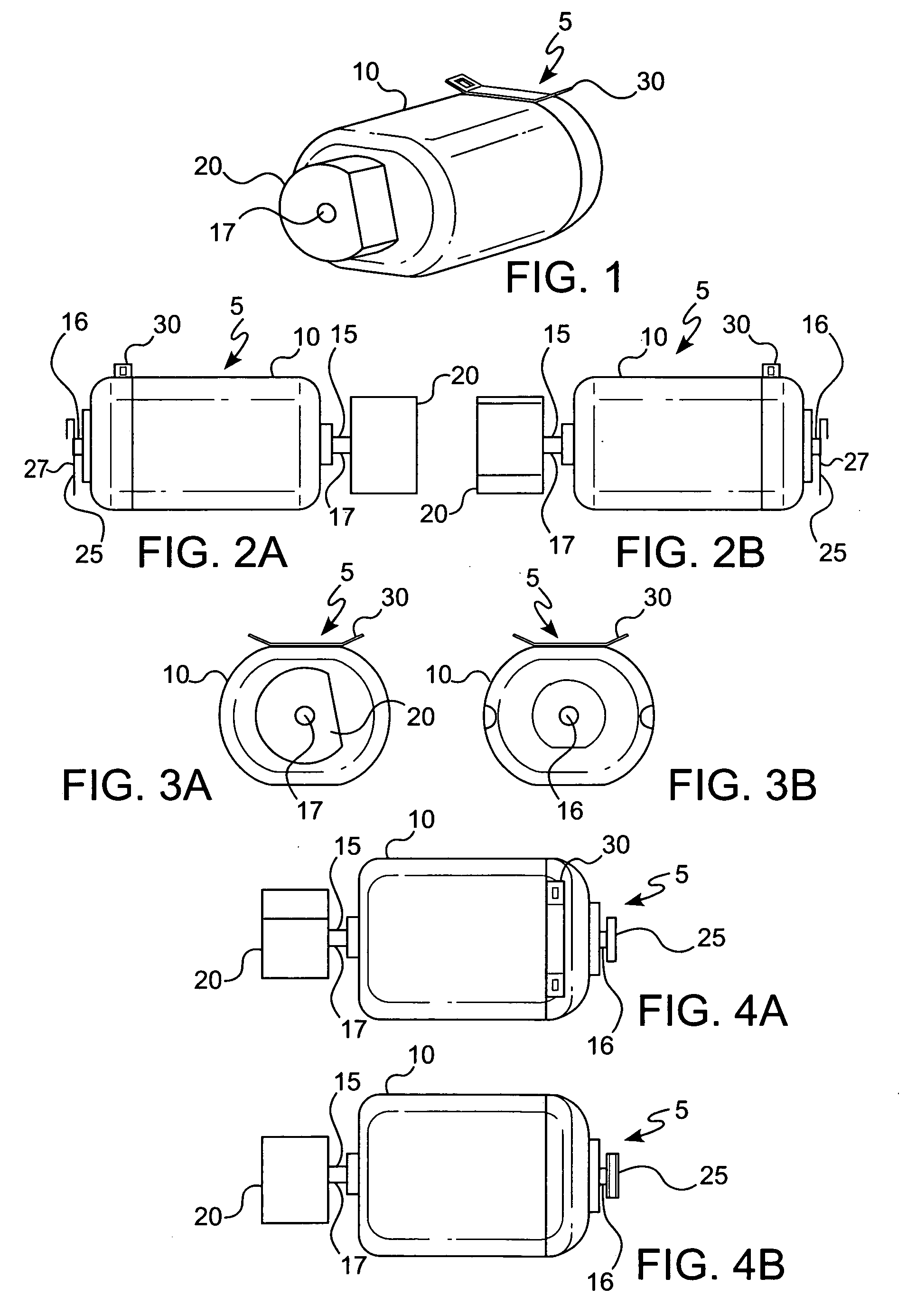
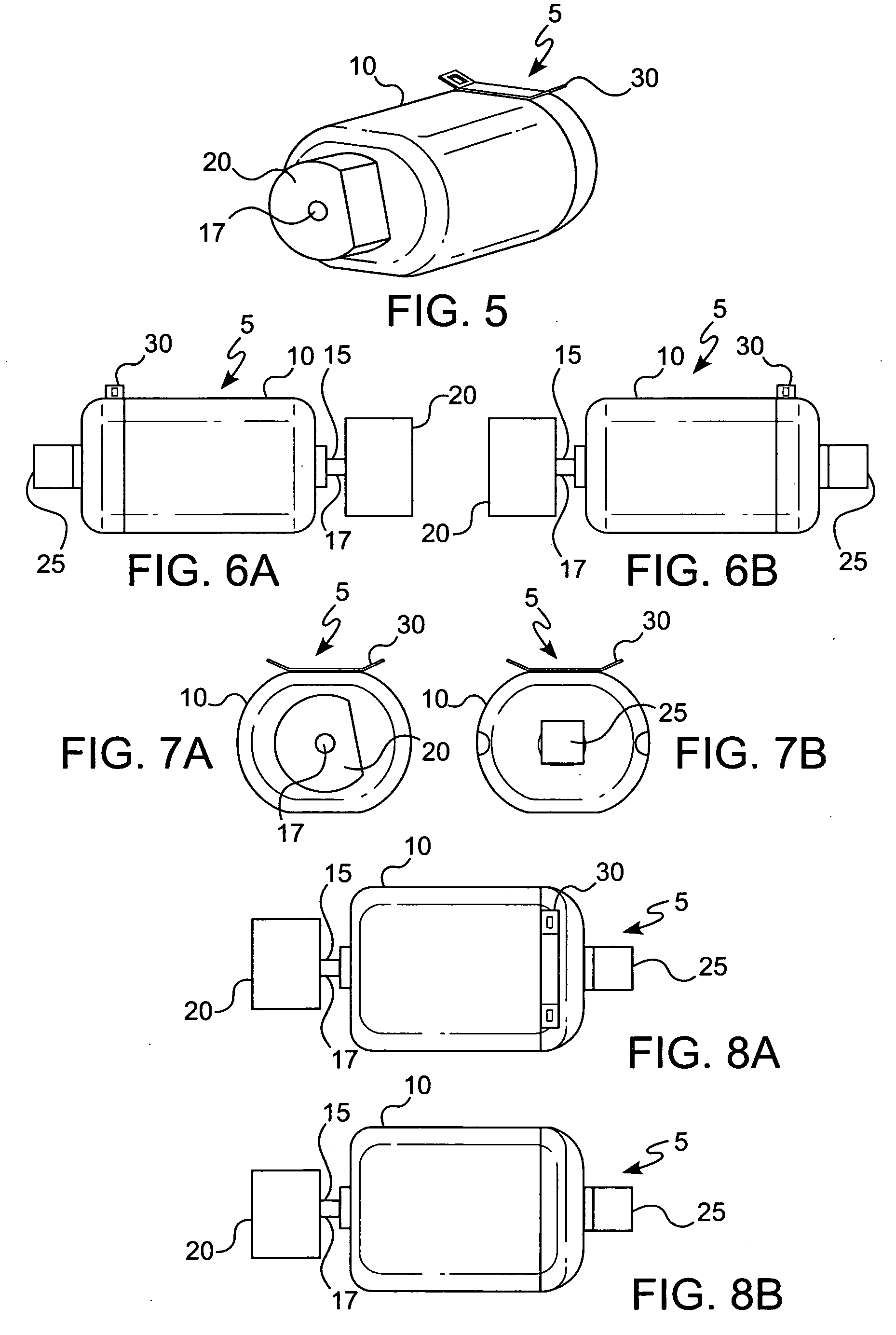
[0045]FIGS. 1 through 8B illustrate two preferred embodiments of a motor assembly (5) according to the present invention, each with a different form of a pressure-applying member (25). As shown in FIGS. 1 through 8B, the present invention preferably encompasses a motor assembly (5) comprising a motor (10) and a drive shaft (15) extending through the motor (10). The drive shaft (15) has a first end (16) and a second end (17) (shown best in FIGS. 2A, 2B, 6A, and 6B). The drive shaft's (15) first end (16) exits on one side of the motor (10) and the drive shaft's (15) second end (17) exits on the opposite side of the motor (10). A weight (20), of any mass or size, is secured to the drive shaft's (15) second end (17). Finally, a pressure-applying member (25) abuts the drive shaft's (15) first end (16). The pressure-applying member (25) puts pressure on the drive shaft (15) to stabilize the drive shaft (15) so that the motor assembly (5) produces less noise when the weight (20) rotates. S...


PUM


Abstract

This patent discloses electric motor assemblies for increasing vibratory power with less noise and massage assemblies using the same.

Description

FIELD OF THE INVENTION [0001] The present invention relates to electric motor assemblies for increasing vibratory power with less noise and massage assemblies using the same. BACKGROUND OF THE INVENTION [0002] Numerous massage devices are commercially available to be used by laypersons as well as by trained professionals, such as physical therapists, doctors, and chiropractors. Generally, such devices comprise: (i) an electric motor, (ii) a weight or mass, (iii) a power source, including but not limited to, standard or rechargeable batteries or an AC adaptor, (iv) a treatment head, and (v) a means for holding or manipulating the massager. Many of these massaging devices create a vibratory sensation to stimulate the skin, muscle, body parts, etc. to which they are applied. [0003] Designers, manufactures, consumers, and users of such massage devices often face a trade-off between the power and the noise of the massage devices. Increasing the power or the force of the vibrations of a m...

Claims


Application Information

Patent Timeline
01 Sep 2005
Publication
US20050192519A1
IPC
A61H1/00; A61H23/02
CPC
A61H23/0263
Inventors
CRUNICK, JOHN