
Methods and systems for performing horological functions in commercial transactions using time cells

a technology of time cells and commercial transactions, applied in the field of horology, can solve the problems of affecting the design of electronic devices, affecting the accuracy of horological functions,

Inactive Publication Date: 2005-09-01
IBM CORP
View PDF31 Cites 22 Cited by
  • Summary
  • Abstract
  • Description
  • Claims
  • Application Information

AI Technical Summary

Benefits of technology

[0012] A method, an apparatus, a system, and a computer program product for controlling a commercial transaction is presented. An article of manufacture has a time cell that is read by an electronic apparatus. In response to a determination of a state of the time cell by the electronic apparatus, usage of the article of manufacture in a commercial transaction is enabled or denied based on the determined state of the time cell. The expiration period of a time cell controls the time period during which the commercial transac

Problems solved by technology

Chemical batteries present potential chemical leak and disposal hazards and are relatively expensive compared to the cost of fabricating a tiny electronic circuit.
Batteries tend to have a short shelf life, especially compared to the useful life of the electronic circuits that they accompany.
In addition, batteries are sometimes several times larger than the electronic circuit to which they are connected, thereby placing design restrictions on the electronic device.
Electronic time base oscillators are assumed to be necessary for small, electronic, horological devices, but the accompanying batteries have many inherent disadvantages.
Although a time cell has an inherent disadvantage because the time cell itself does not have an externally perceivable indicator, in which case a human cannot directly observe and interpret an indicator for an elapsed time period as measured by the time cell, a time cell is still useful for many applications or products in which a display of the timekeeping substance or device is not necessary.

Method used


Image

  • Methods and systems for performing horological functions in commercial transactions using time cells
  • Methods and systems for performing horological functions in commercial transactions using time cells
  • Methods and systems for performing horological functions in commercial transactions using time cells

Examples


Embodiment Construction

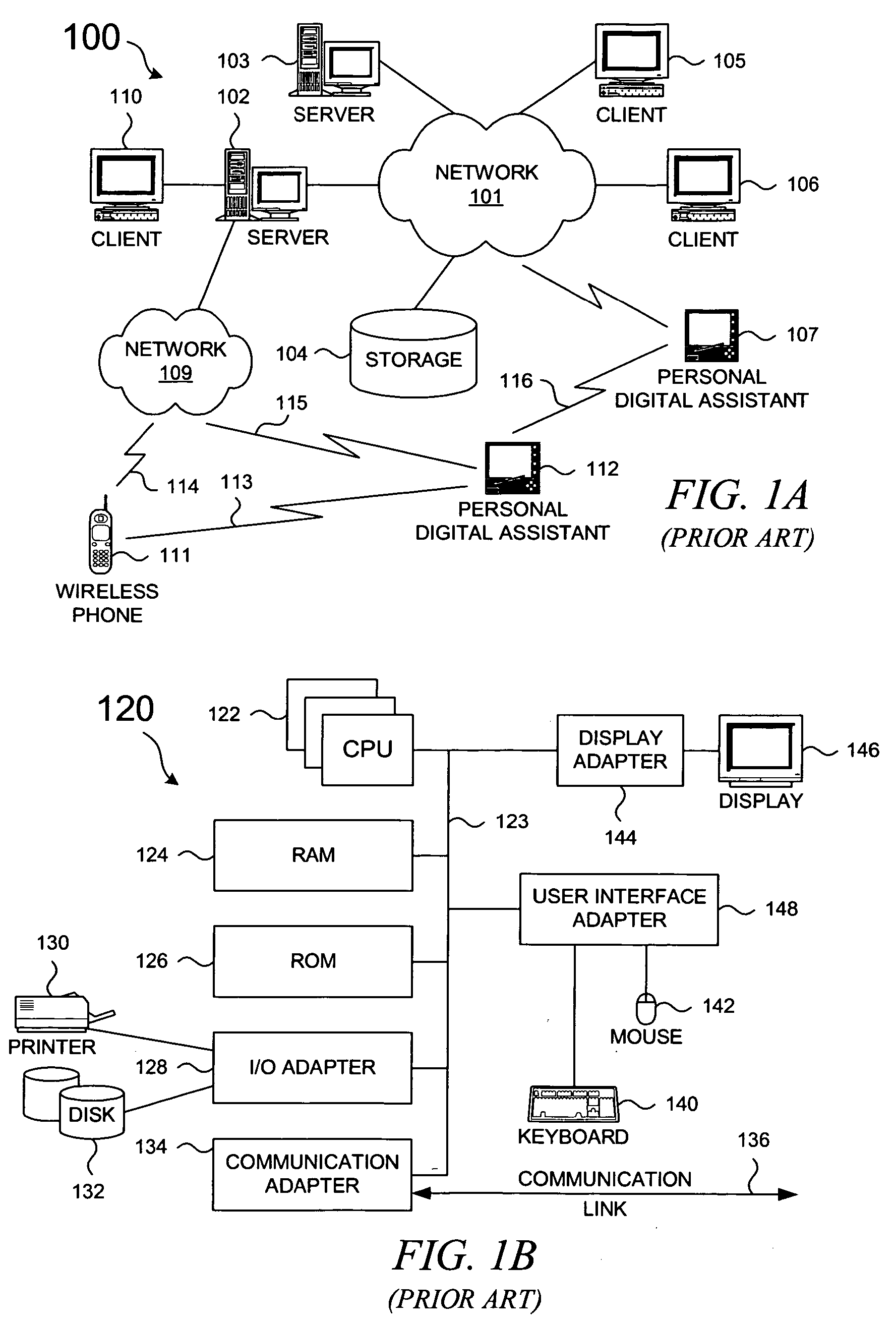
[0034] In general, the devices that may comprise or interact with the present invention include a wide variety of data processing technology. Therefore, as background, a typical organization of hardware and software components within a distributed data processing system is described prior to describing the present invention in more detail.

[0035] With reference now to the figures, FIG. 1A depicts a typical network of data processing systems, each of which may support a device that comprises the present invention or which may implement the present invention or a portion of the present invention. Distributed data processing system 100 contains network 101, which is a medium that may be used to provide communications links between various devices and computers connected together within distributed data processing system 100. Network 101 may include permanent connections, such as wire or fiber optic cables, or temporary connections made through telephone or wireless communications. In t...


PUM


Abstract

A method and system for controlling a commercial transaction is presented. An article of manufacture has a time cell that is read by an electronic apparatus. In response to a determination of a state of the time cell by the electronic apparatus, usage of the article of manufacture in a commercial transaction is enabled or denied based on the determined state of the time cell. The expiration period of a time cell controls the time period during which the commercial transaction is enabled or is denied to be performed; an unexpired time cell may both enable or deny performance of a commercial transaction, and an expired time cell may also both enable or deny performance of a commercial transaction. The time cell may be used to restrict the usage period of a coupon, a promotional offer, a pre-paid service, or some other commercial transaction that involves an article of manufacture.

Description

CROSS-REFERENCE TO RELATED APPLICATIONS AND PATENTS [0001] The present patent application is related to the following co-pending patent application and hereby claims priority as a continuation-in-part application: U.S. patent application Ser. No. 11 / 059,279, filed Feb. 15, 2005, titled “Methods and Systems for Performing Horological Functions Using Time Cells”, which is related to the following patents as a continuation patent application: U.S. Pat. No. 6,856,581, issued Feb. 15, 2005, titled “Batteryless, Oscillatorless, Binary Time Cell Usable as an Horological Device with Associated Programming Methods and Devices”, from which the present patent application claims priority as a continuation application; U.S. Pat. No. 6,831,879, issued Dec. 14, 2004, titled “Batteryless, Oscillatorless, Analog Time Cell Usable as an Horological Device with Associated Programming Methods and Devices”; U.S. Pat. No. 6,829,200, issued Dec. 7, 2004, titled “Sensing Methods and Devices for a Batteryles...

Claims


Application Information

Patent Timeline
IPC IPC(8): G04F1/00G04F10/10
CPCG04F10/10G04F1/005
Inventor BERSTIS, VIKTORS
Owner IBM CORP
Learn More