CDR-based clock synthesis

a clock synthesis and clock technology, applied in the field of clock synthesis, can solve the problems of frequency pulling becoming more pronounced at higher integration levels, requiring additional components and associated costs,

Active Publication Date: 2005-09-01
MAXLINEAR INC +1
View PDF14 Cites 18 Cited by
  • Summary
  • Abstract
  • Description
  • Claims
  • Application Information

AI Technical Summary

Problems solved by technology

Thus, such analog implementations either occupy a large amount of die area within the transceiver, or must be implemented externally of the transceive...

Method used


Image

  • CDR-based clock synthesis
  • CDR-based clock synthesis

Examples


Embodiment Construction

[0010] A clock source can be thought of as a periodic data stream. Given a data rate of fD, a clock source with a frequency of fD / (2×n) can be thought of as a periodic data stream with a (100 / n) percent transition density. For example, clocks at frequencies of 1.25 GHz (n=1), 625 MHz (n=2), and 417 MHz (n=3) are all 2.5 Gb / s periodic data streams with respective transition densities of 100%, 50% and 33%.

[0011] Performing CDR on a clock input is equivalent to recovering its frequency while attenuating its noise content. Unlike random data, a clock has a fixed (i.e., generally constant over time) transition density, so the CDR circuit can use a lower bandwidth than would be required for random data, thereby permitting rejection of phase noise at lower frequencies.

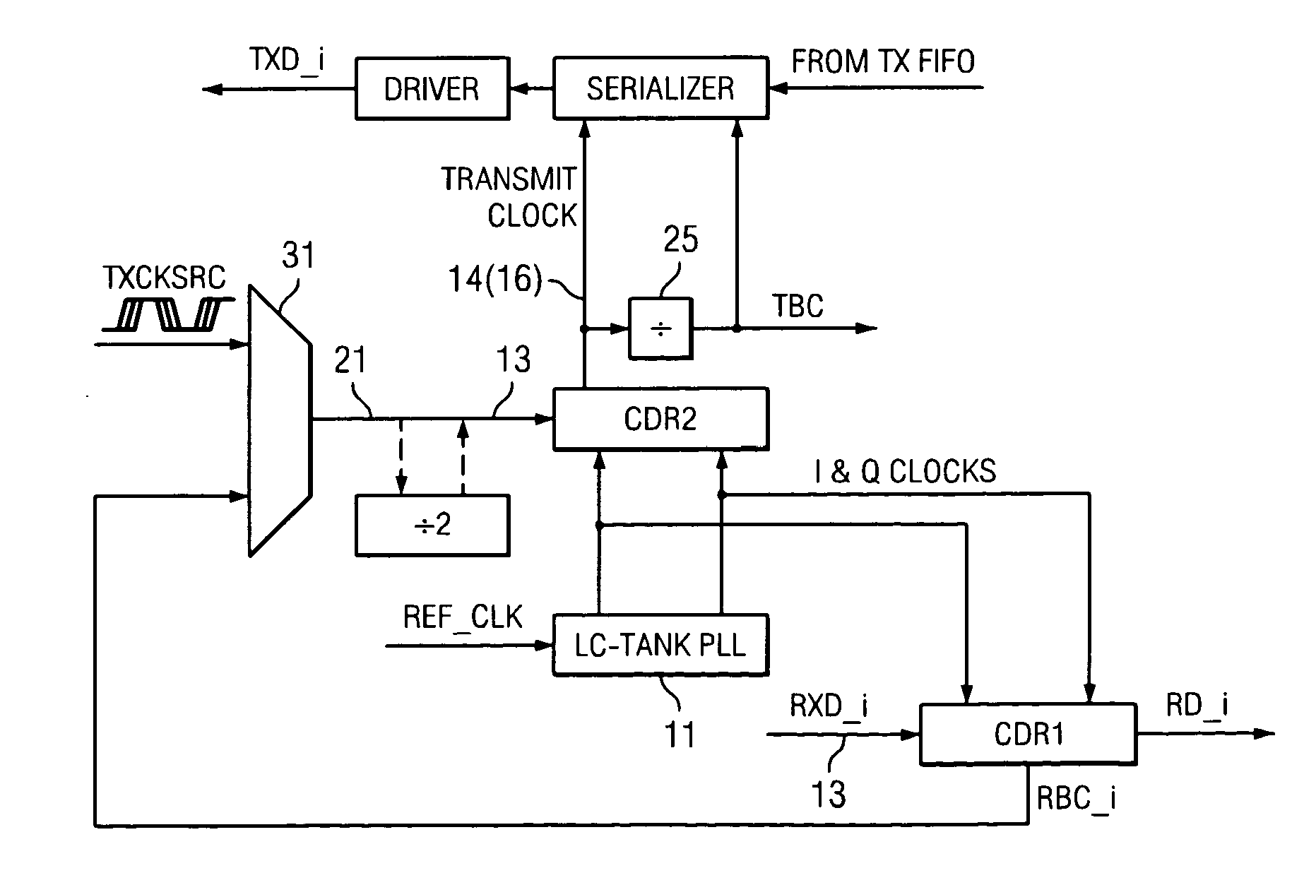
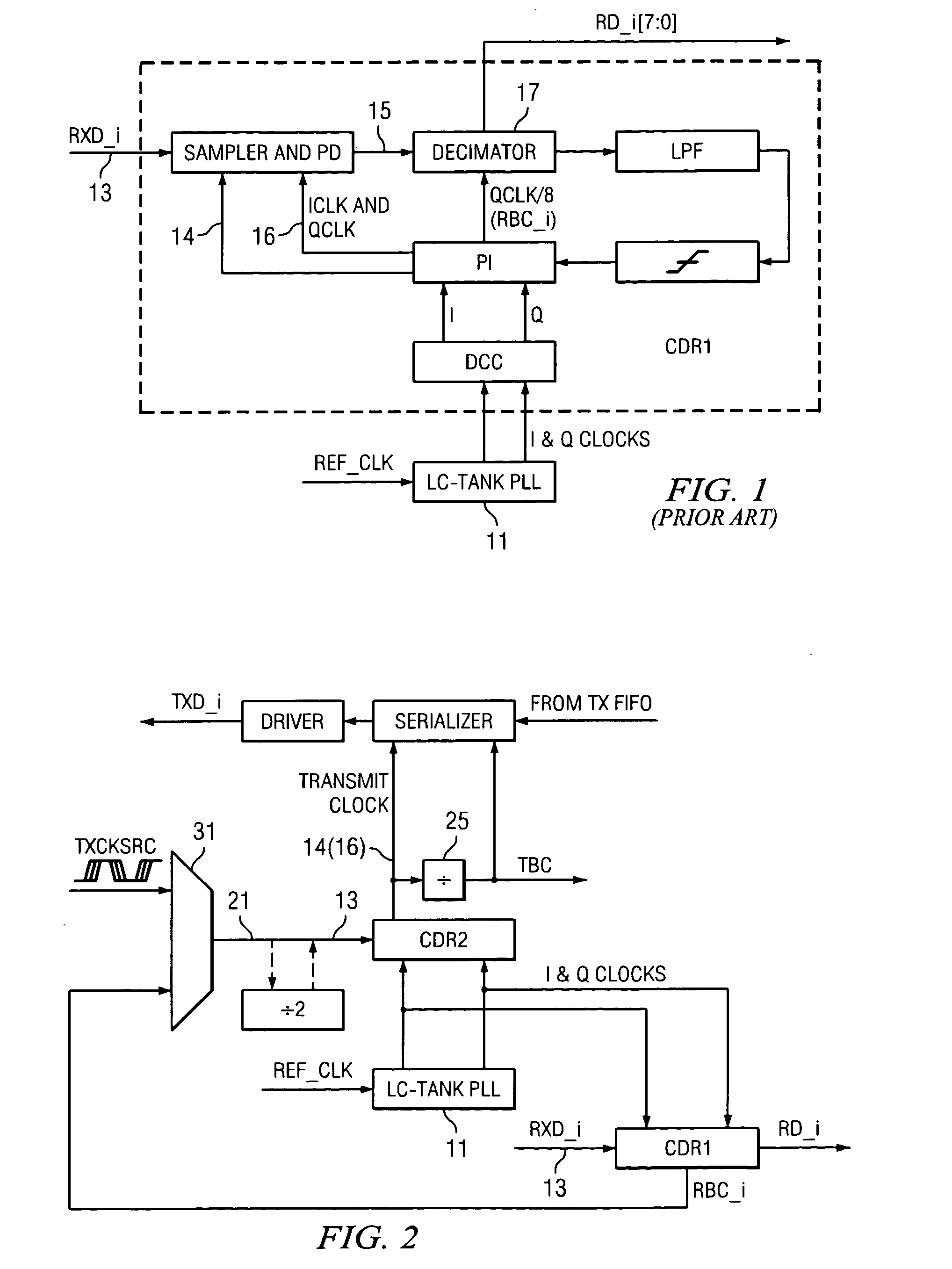
[0012]FIG. 2 diagrammatically illustrates pertinent portions of exemplary embodiments of a serial data transceiver according to the invention. A noisy external clock source (TXCKSRC) can be applied (e.g., via selector...


PUM


Abstract

A clock signal can be synthesized by performing a clock and data recovery (CDR) operation on a potentially noisy clock source signal which has a known transition density. The CDR operation produces a desired clock signal in response to the clock source signal. In order to reduce crosstalk between plesiochronous receive and transmit clock domains of a serial data transceiver, a single common PLL is used both to recover the receive clock from the received data and to synthesize the transmit clock from a potentially noisy transmit clock source signal.

Description

FIELD OF THE INVENTION [0001] The invention relates generally to clock synthesis and, more particularly, to CDR (clock and data recovery)-based clock synthesis. BACKGROUND OF THE INVENTION [0002] Conventional serial data transceivers are operable for transmitting and receiving serial data on a communication medium. Serial data transmission is controlled by a transmit clock signal. The transceiver device receives as an input a potentially noisy external clock source, and produces the transmit clock signal in response to this external clock source. The noisy external clock source is typically cleaned up by applying thereto a narrow-band filtering operation. Conventional approaches implement the narrow-band filtering with an analog implementation, which requires large capacitors. Thus, such analog implementations either occupy a large amount of die area within the transceiver, or must be implemented externally of the transceiver, thereby necessitating additional components and associat...

Claims


Application Information

Patent Timeline
IPC IPC(8): G01R31/28H03L7/06H04L7/00H04L7/033
CPCH04L7/0091H03L7/06
Inventor PARTOVI, HAMIDEVANS, WILLIAM P.
Owner MAXLINEAR INC
Why Eureka
Try Eureka